|
|
Chapter 3
Basic Factors of Biodynamics and Joint Stability
From R. C. Schafer, DC, PhD, FICC's best-selling book:
“Clinical Biomechanics: Musculoskeletal Actions and Reactions”
Second Edition ~ Wiliams & Wilkins
The following materials are provided as a service to our profession. There is no charge for individuals to copy and file these materials. However, they cannot be sold or used in any group or commercial venture without written permission from ACAPress.
All of Dr. Schafer's books are now available on CDs, with all proceeds being donated
to chiropractic research. Please review the complete list of available books.
Structural Motion

Kinematics

Summary of Major Static and Kinetic Factors Influencing Mechanical Efficiency of Muscular Effort

Biomechanical Stress

Biomechanical Aspects of Articular Cartilage
Chapter 3: Basic Factors of Biodynamics and Joint Stability
The techniques used for analyzing static positions of the body are only approximate inasmuch as forces accompanying movement incorporate such dynamic factors as acceleration, momentum, friction, the changing positions of rotational axes, and the resistance and support offered by tissues other than muscles. This chapter discusses the basic concepts and terms of biodynamics, biomechanical stress, and the biomechanical aspects of articular cartilage pertinent to the clinical setting.
Structural MotionThe study of dynamics is concerned with loads and the motions of bodies (kinematics) and the action of forces in producing or changing their motion (kinetics). Kinematics lets us describe the characteristics of motion position, acceleration, and velocity such as in gait or scoliotic displacements. Here we are concerned with the position of the center of mass of the body and its segments, the segmental range of motion, and the velocity and direction of their movements. In kinetics, we become concerned with the forces that cause or restrict motion such as muscle contraction, gravity, and friction. A complete biomechanical analysis of human motion or motion of a part would include both kinematic and kinetic data.
Motion can be defined as an object's relative change of place or position in space within a time frame and with respect to some other object in space. Thus, motion may be determined and illustrated by knowing and showing its position before and after an interval of time. While linear motion is readily demonstrated in the body as a whole as it moves in a straight line, most joint motions are combinations of translatory and angular movements that are more often than not diagonal rather than parallel to the cardinal planes. In addition to muscle force, joint motion is governed by factors of movement freedom, axes of movement, and range of motion.
Degrees of Freedom
JOINT AXES
As previously discussed, the body is composed of numerous uniaxial, biaxial, and multiaxial joints. Joints with one axis have one degree of freedom to move in one plane such as pivot and hinge joints, joints with two axes have two degrees of freedom to move in two different planes, and joints with three axes have three degrees of freedom to move in all three planes, eg, the ball-and-socket joints. Thus, that motion in which an object may translate to and fro along a straight course or rotate one way or another about a particular axis equals one degree of freedom.
In Chapter 1, joint classification was given under the major divisions of synarthrodial, amphiarthrodial, and diarthrodial joints. This is the classic anatomic classification. However, from a purely biomechanical viewpoint, joint motion can be reduced to just two types: (1) ovoid, which permits motion in one plane, X; and (2) sellar, which permits motion in two planes, Y and Z (Fig. 3.1).
JOINT FREEDOM
To know the actual degrees of freedom available to a part of the body, one must sum the degrees available of adjacent joints to appreciate the amount of free motion of one part relative to another part. The degrees of freedom of a fingertip relative to the trunk, for example, are the sum of the degrees of freedom of all the joints from the distal phalanges to the shoulder girdle. While the distal phalanges have only one degree of freedom, the entire extremity has 17 degrees in total. This summation process is an example of a living, open kinematic chain.
COMBINED MOVEMENTS
Simple translatory motions of a body part involve movements of more than one joint. This requires reciprocating actions of three or more segments at two or more joints if parallel lines are to be followed. For example, a fingertip cannot be made to follow the straight edge of a ruler placed in front if the wrist and elbow joints are locked. If the wrist and elbow are fixed, the fingertip must follow an arc and not a straight line. Thus, human motion can be described as translatory motion that has major contributions from linear, angular, and curvilinear motions. The term general or three-dimensional motion implies that an object may move in any direction by combining multidirectional translation and multiaxial rotation.
Plane and Out-of-Plane Motion
PLANE MOTION
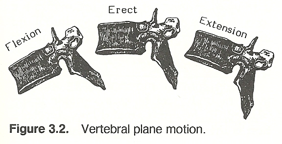
Any motion in which all coordinates of a rigid body move parallel to a fixed point is referred to as plane motion. Such motion has three degrees of freedom; eg, sliding A-P, sliding lateral, and spinning. In other words, plane motion has two translatory degrees of motion along two mutually perpendicular axes and one rotatory degree of motion around an axis perpendicular to the translatory axes. For instance, if a person curves his trunk forward, the thoracic vertebrae flex and rotate in a single plane about an axis that is perpendicular to the sagittal plane (Fig. 3.2). In such plane motion, various points on a particular vertebra move in parallel planes.
THE INSTANTANEOUS AXIS OF ROTATION
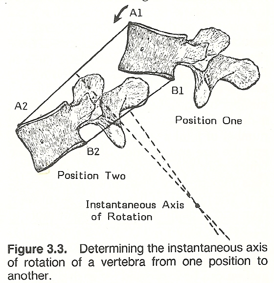
Plane motion is described by the position of its instantaneous axis of rotation and the motion's rotatory magnitude about this axis. In the above example of cervical flexion, for instance, as a vertebra moves in a plane, there is a point at every instant of motion somewhere within or without the body that does not move. If a line is drawn from that point so it perpendicularly meets the line of motion, the point of intersection is called the instantaneous axis of rotation for that motion at that particular point in time (Fig. 3.3). Most joint movement is to a great degree rotatory motion, but the axis of motion may change its location and/or its orientation during a complete range of motion.
OUT-OF-PLANE MOTION
As contrasted to plane motion, out-of-plane motion is a version of general body motion with three degrees of freedom consisting of two rotations about mutually perpendicular axes and a translation perpendicular to the plane formed by the axes. Thus, in out-of-plane motion, the body moves more than in a single plane. For example, if a person bends laterally, a midthoracic vertebral body translates from the sagittal plane towards the horizontal plane (Fig. 3.4). This is not plane motion because various points on the vertebra do not move in parallel planes.
Range of Motion
A freely moving body such as a vertebra has six degrees of freedom as it moves in three-dimensional space: eg, translations along and rotations about each of the three cardinal axes. The range of motion (ROM) of a joint is the quantities that indicate two points at the extreme range of physiologic rotation and translation for each of the joint's six degrees of freedom. Thus, the range of motion is the difference between the extremes of physiologic motion. It is measured in linear units for translation and in degrees for rotation.
An articulation may have several degrees of freedom and a most limited range of motion, and a joint with one degree of freedom may have a large range of motion. Keep in mind that degrees of freedom refer to the ability to move in planes (ie, the number of axes), while range of movement is dependent upon soft-tissue restraints, the number of joint axes, the joint architecture, and the size and position of adjacent tissue which may affect motion of a part (eg, biceps hypertrophy restricting forearm flexion). The knee joint has one degree of freedom and a relatively large range of motion; L5 has six degrees of freedom and a most restricted range of motion. In a joint having one or more degrees of motion, a range of motion can be expressed for each degree.
Kinematics
Kinematics, without considering the forces involved, is the study of the motion of objects, with emphasis on displacement, acceleration, and velocity. Many of the concepts previously discussed such as coordinate systems, translation, rotation, coupling, degrees of freedom, range of motion, and axes of motion are major concerns within kinematics. The importance of this sometimes complex study is underscored in the analysis and management of structural problems of the body, in understanding trauma and clinical stability, in coping with spinal imbalance and other postural problems, and in evaluating orthopedic x-ray films.
It might be helpful here to review some major terms of kinematics. Motion infers a continuous change (displacement) of position. Translation refers to movement where various points in an object at a specific interval of time have the same direction of displacement relative to some fixed point. Rotation (spinning or angular motion) refers to movement where various points in a straight line in an object (or a hypothetical extension of such a line) at a specific interval of time have a velocity of zero relative to some fixed point. Rotation involves angular displacement of an object about some axis that is located within or exterior to the revolving object and where the points of the object describe concentric circles around an axis. Coupling is motion in which translation or rotation of an object along or about an axis is constantly related to simultaneous translation along or rotation about another axis.
Acceleration
The application of Newton's second law is an important facet of kinematic studies. That is, a net force acting on the body gives it an acceleration that is proportional to the force in both direction and magnitude and inversely proportional to the body's mass.
LINEAR ACCELERATION
During human movement, the importance of body weight as a variable is explained in Newton's second law. Acceleration is the rate of change in velocity of an object. The greater a person's mass, the greater his or her equilibrium as measured by the quantity of force necessary to accelerate it positively or negatively. Thus, a heavy body has the advantage in maintaining a state of equilibrium, but it has a disadvantage in producing acceleration. This is exhibited in the weight need of a wrestler vs that of a sprinter. Also, the analysis and treatment of gait disorders and the application of braces and supports, for example, depend on the mechanical parameters of acceleration, displacement, and velocity.
ANGULAR ACCELERATION
Angular acceleration is produced by a force when its line of action does not pass through the center of rotation. The further the distance is between the line of action and the center of rotation, the more effective is the force in producing angular motion (moment, torque). The same factors involved in kinematic and kinetic translational relationships apply to rotational motion if we substitute moment of inertia for mass, moment of force for force, angular change for displacement, and moment for force.
Angular acceleration is the rate of change of angular velocity. Neither a body in linear motion or a rotating body needs to have a uniform angular velocity. If a body's angular velocity changes to a new value in a time frame, the angular velocity is changed (Fig. 3.5). The unit of measurement of angular acceleration's magnitude is in degrees or radians per second per second. Mathematically, angular acceleration equals the new angular velocity minus the original angular velocity times the time involved.
In rotational movements, moment = mass moment of inertia X angular velocity. This physical property reflects how mass is distributed about an axis, and it is concerned with differences in motion by various rotating body segments. The moment of inertia of a body will differ about its various axes because the motion of any one segment for a specific angular rotation is determined by the distance of that part from the center of rotation. For example, when an automobile is struck from the rear, the trunk of a person in the car is accelerated forward in relation to the head. The head responds slower than the trunk because of its inertia, and it is angularly accelerated backward. Thus, the mechanism of cervical whiplash injury is determined by the angular acceleration of the head and its inertia.
Velocity
Kinematic analyses invariably incorporate the concepts of linear velocity, angular velocity, and instantaneous velocity. When velocity increases, acceleration is said to be positive; when velocity decreases, acceleration is negative.
LINEAR VELOCITY
Linear velocity is an object's rate of linear position change. The term speed refers to velocity's magnitude. If acceleration is constant and an object starts moving from rest, the final velocity that will be required will be directly proportional to the duration of the event. As a position change is measured by changes in distance or length, linear velocity = distance/time. If a muscle shortens 3 inches in half a second during contraction, the contraction's linear velocity is 6 inches/second.
ANGULAR VELOCITY
Angular velocity occurs when the motion is rotation. A thrown ball always has a linear velocity, and it may have an angular velocity if it spins. A spinning top always has an angular velocity, and it may have a linear velocity if it simultaneously moves across a surface.
When a bony lever is moved by a muscle, the length of the lever can be considered the radius of a circle. The difference between a starting position and a stopping position can be measured by the angle formed. Thus, angular velocity equals the angle turned through per unit of time. A radian is a unit of angular measurement which is commonly used to describe angular velocity that is defined as the ratio of arc length to the length of the radius.
All but a few body movements are rotations of bones about their joints, and these rotations are seldom confined to one simple arc. Rather, they tend to vary irregularly to compensate for the restrictions of other joints and for the transfer of power from one set of muscles to another. During such irregular rotations, the bones also twist about their own axes. For example, during walking, the legs not only move forward and backward, they also rotate laterally during the forward swing, during contact of the foot with the ground, and again during the recovery phase of the stride.
In addition, all human movement is governed by the positive and negative acceleration of joint actions. During locomotion, for instance, the thigh changes its linear and angular positions and its velocities during gait. Linear acceleration during straight-line locomotion is partially produced by the increased angular velocity (angular acceleration) of the lower extremities. In all joint movements, the principle that linear acceleration equals the product of the radius and the angular acceleration applies.
INSTANTANEOUS VELOCITY
Both linear and angular velocity are vector quantities because they have magnitude and direction. The term instantaneous velocity is the average velocity when the time interval approaches zero. It is measured in linear units per second. An object moving toward a goal may not have consistent speed and direction; eg, an automobile driving up a winding and dipping road to reach the summit of a hill. At any instant in time, both acceleration and direction may be above or below the average for the journey. Thus, an accurate description of velocity may necessitate the full plotting of its instantaneous velocity vectors.
Kinematic Analyses of Human Motion
Frame-by-frame motion pictures of a body or cineroentgenology of a region in motion can be analyzed to gain a great appreciation of human movement. The problem is often to determine the levers involved in each joint action and compute the types of external load and internal stress involved. This analysis should incorporate at least the following data:1. The name of the movement under study, the time frame (frame number) at which the movement is initiated and concludes, and the joint or joints at which movement occurs.
2. The segment or segments (lever) making up the kinematic chain being moved that are the effect of joint action should be described.
3. The force or forces causing the movement and the point of force application should be described. These forces would include such factors as gravity, isotonic or concentric muscle shortening, or some other force contributing to the production of movement.
4. The force or forces offering resistance to the movement and the point of force application should be described. These forces would include such factors as gravity, eccentric muscle lengthening while exerting tension, or some other force contributing to movement resistance.
5. A description of the stabilized and/or relaxed joints in the lever and the forces which stabilize these articulations.
6. A description of the adjacent stabilized and/or relaxed joints outside the lever and the forces which stabilize these articulations.
When more sophisticated data are desired, body markers (often illuminated), specialized photographic equipment, timing devices, and electromyographic and electrogoniometric appliances can be used to:
1. Plot the trajectory (X vs Y axes) for each body marker, and Y coordinate for each marker in relation to time.
2. Plot velocity and/or acceleration of each marker relative to time.
3. Plot joint angles, angular velocity, and/or angular acceleration relative to time or instant of movement cycle.
4. Plot average velocity in terms of direction, movement length, and range of movement.
5. Plot the angle or one joint against another at various intervals of time.
Body Links
During human motion, several moving segments are involved in each study where one segment moves on one adjacent which moves on another. This is similar to engineering links that involve overlapping segments held together by pins (joints) which serve as axes of rotation. Such overlapping does not occur in the human body except in a few places such as at the ankle and the C1-odontoid articulation.
A link is a straight line (eg, a rod) of constant length that extends from axis to axis (Fig. 3.6). Such a system of links can serve as a geometric model to analyze motion. If power is to be transmitted, the links of a machine must form a closed system where each link has a particular relation to every other link in the system. The closed system guarantees that forces are transmitted in a positive and predictable manner.
OPEN BODY SYSTEMS
The body can be thought of as a system of body links which form one or more kinematic chains. Most skeletal links are open chains rather than closed systems. This is because the distal ends of the extremities are free (unconnected to another link).
The dimensions of human links are determined by the length of bone from joint axis to joint axis. The joint axes are used because few articulations have overlapping bones. In kinematic analysis of human motion, the rotational axes are not located at the bony junctures. For example, the axis of the shoulder is within the humeral head; that of the hip, within the femoral head. In the knee and elbow, the axes are proximal to the articulating surfaces.
As mentioned earlier in the discussion of degrees of freedom, a proximal link in a segmental chain cannot be moved without causing displacement in one or more adjacent links. Thus, the "lever" in gross body movements is the kinematic chain involved, which is made up of a number of linked levers. Hip flexion and extension, for example, is not determined solely by the skeletal lever of the femur. When a person takes a step, the pelvis, hip, thigh, knee, leg, ankle, foot, and toes are involved.
In addition to the segmental levers involved in body movement and the forces producing the movement, consideration must be given to muscular and other softtissue forces which stabilize a segment involved in the kinematic chain. It is for this reason that a kinematic analysis must include a description of the stabilized joint both within and without the lever and the forces which stabilize the involved articulations.
CLOSED BODY SYSTEMS
While most kinematic chains in the body are open systems, there are two excellent examples of closed systems which are of special interest in chiropractic. One is found in the thoracic cage where the dorsal spine, upper ten ribs, and sternum are united by the costovertebral and costosternal joints to form a closed kinematic chain. No movement of one segment can be made that does not affect the other in a predictable manner. The other example is found in the pelvic girdle where the ilia and sacrum are united by the sacroiliac and pubic joints to form a closed kinematic chain. Again, no movement of one segment can be made that does not affect the others.
Of course, the body as a whole or a part could be considered a closed system if the ends of the system are fixed. For instance, when a person tries to dislodge the overlapping bumpers of two cars, the person's feet are fixed to the ground by body weight and lifting compression and the hands are fixed by the weight of the car being lifted. The same principle applies when trying to displace any firmly fixed object (Fig. 3.7). One can appreciate that this concept has several implications in the analysis of fixated and ankylosed vertebrae during spinal movement.
Segmental Parameters
It is frequently important in kinematic and kinetic studies to know the center of mass for a particular body part as well as the body as a whole which is located slightly anterior to S2. Most researchers utilize the segmental centers of mass loci determined by Dempster with slight adaptations. See Table 3.1. The average weight percentages for body segments are shown in Table 3.2.
KinematicsMuscles are the primary source of force within and gravity the primary source without the body to produce motion of the body. As with kinematics, kinetic analyses are essentially based on Newton's laws of motion.
Several methods are used by the research scientist in analyzing kinetic problems. Briefly, these include the application of acceleration, impulsemomentum, and work-energy factors. An acceleration approach is used in kinetics to analyze either linear or rotational forces and instantaneous acceleration problems. An impulse-momentum approach is used to analyze force acting over a time duration, and it is essential in problems of falls or when two or more objects collide. A work-energy approach is used in kinetics to analyze forces known as a function of body position and the forces are acting over a distance. While detailed descriptions of these approaches are beyond the scope of this text, several basic concepts and concerns of kinetics pertinent to the physician are discussed in this section.
Table 3.1. Locations of Segmental Centers of MassSegment(s) Center of Mass Head, neck, Slightly anterior to the vertebral body of T11. and trunk Head and neck On the occipital bone's under surface or within from 3/4" to 1-1/8" from the crest of the dorsum sellae. Head Within the sphenoid sinus, about 3/16" past the anteroinferior edge of the sella turcica. ------------------------------------------------------------------------------- Upper limb Slightly above the elbow joint. Arm Within the medial head of the triceps adjacent to the radial groove, about 3/16" proximal to the far end of the deltoid insertion. Forearm About 1/2" proximal to the distal aspect of the insertion of the pronator teres and 3/8" anterior to the interosseous membrane. Hand On the axis of the 3rd metacarpal, nearly centered between the volar and palmar skin at the angle formed between the radial longitudinal and proximal transverse crease of the palm. ------------------------------------------------------------------------------- Lower limb Slightly above the knee joint. Thigh Within the adductor muscles, 1/2" medial to the linea aspera, below the adductor canal, 1-3/16" beneath the apex of the femoral triangle, and 3/4" proximal to the farthest fibers of the adductor brevis. Leg About 1-1/2" under the popliteus at the posterior aspect of the posterior tibialis, 5/8" superior to the proximal aspect of the Achilles tendon, and 3/8" posterior to the interosseous membrane. Foot On a line between the center of the ankle joint and the ball of the foot in the plane of the 2nd metatarsal; either within the plantar ligaments or just superficial to the adjacent deep foot muscles, below the proximal halves of the 2nd and 3rd cuneiform bones.
Table 3.2. Average Weight of Body Segments
                            Percentage
                            of Total
     Segment                Body Weight
     Head                       7.3
     Trunk                     50.7
     ---------------------------------
     Arm                        2.6
     Forearm                    1.6
     Hand                       0.7
     ---------------------------------
     Thigh                     10.3
     Leg                        4.3
     Foot                       1.5
Note: The above computations are based on a 150-lb male mesomorph.
The different size, quantity, and length of muscle fiber structure govern
the force which a muscle can produce and the distance which a muscle can contract. Most of these characteristics are genetically determined by usual body
needs such as the strength and range of motion required.
(1) the length of the lever arms,
(1) the magnitude of the forces, and
Obviously, the design of the musculoskeletal system is such that the majority of muscles pull at an angle against the bones they move. The resultant of
two forces acting at an angle to each other can be computed rather simply by
constructing a parallelogram of forces. This method, shown in Figure 3.14, shows
the anterior and posterior fibers of the deltoid acting through a common tendon
inserted into the humerus to abduct the humerus. The diagonal of the parallelogram represents the resultant of the two forces. If the resultant force of 100
lb in Figure 3.14 is in the direction of the pull of the middle deltoid, and if
it is exerting an additional force of 60 lb, then the total force of all three
deltoid parts acting on the common tendon is 160 lb. Gravity. Although the gravitational force acting at the center of mass of
any body segment is a constant, the moment produced is governed by the segmental
centers of rotation and the locations of the centers of the segmental masses. As
the body in motion is constantly changing position of its segments, the gravitational moments are constantly changing.
Reaction forces. In simple walking, this is expressed as the reaction
force exerted by the ground surface against the foot.
Inertia. The inertial force of a body segment is proportional to segmental acceleration, but it acts in the opposite direction of the segmental acceleration.
Opposing muscle mechanisms are readily seen during the walking cycle. Just
prior to heelstrike, for example, gravity, surface reaction forces, and inertia
are producing an extension (counterclockwise) moment about the knee. However,
the knee flexors, principally the hamstring group and gastrocnemius, are essentially two-joint muscles so that when knee flexion is produced they also produce hip extension (hamstrings) and plantar flexion (gastrocnemius).
Clinical stability refers to the body's ability under load to limit various
patterns of potential displacement in order to prevent damage or irritation to
its components. In the spine, for instance, this is the ability of the vertebral
column and its associated tissues to avoid cord, nerve, vascular, lymphatic,
ligament, disc, or muscle irritation, stretch, pressure, deformation, or pain as
the result of structural changes from loads (Fig. 3.17). Thus, any disruption of
a musculoskeletal unit decreases the unit's stability in proportion to the degree of structural and physiologic impairment.
Stress equals load divided by the original cross-sectional area. In mechanics, measurement is recorded by pounds/inch524 (psi), newtons/meter524, or pascals.
The two types of stress are normal stress and shear stress. Any stress normal to
a cardinal plane is referred to as a principal stress.
Normal and Shear Strain. Strain equals a change in shape or length divided
by the original length of the structure, thus it represents a change in angle
(Fig. 3.20). This alteration of shape or length is called deformation. There is
no unit of measurement for strain as there is with stress. As with stress, the
two types of strain are normal strain and shear strain. Stress is usually
plotted on the Y axis, while strain is plotted on the X axis.
Flexibility refers to a substance's ability to be flexed and yield without
fracture; thus, its pliability and nonrigidity. The ratio of the quantity of
displacement produced to the load applied is the flexibility coefficient (responsiveness) of the structure. A relatively high flexibility coefficient is
seen in a readily yielding physiologic scoliosis where only small forces result
in large deformities.
Viscosity refers to that property of a substance whereby, when flow occurs
within it, forces arise in such a direction as to oppose the flow. For example,
when the viscosity of synovial fluid becomes higher than normal, friction
increases and movement is inhibited. Mathematically, viscosity is expressed as
the ratio of the shearing stress to the shearing strain rate for viscous solids
or the shearing stress to the velocity gradient for fluids.
In the mechanical sense, elasticity is that springiness or resilience property of a substance that causes it to resist deformation by storing energy and
thereby recovering its original shape and size without permanent deformation by
releasing energy when the deforming forces are removed.
Stiffness is that property of a substance that resists deformation when the
substance is under load. Although similar, stiffness and elasticity are not
opposites. Elasticity is a property of the substance, while stiffness represents
the mechanical behavior, size, and shape of a substance under load. The brittleness of bone is due to its high mineral content.
Plasticity refers to the ability of a substance to retain a permanent shape
attained by pressure deformation beyond its elastic range in any direction without fracture.
All biologic materials have a loading rate where, for example, a slow gradual pull will produce considerable deformation before fracture as contrasted to
a fast pull that produces fracture with little deformation. This loading rate
characteristic concerns the viscoelastic nature of the substance in question
such as bone, fibrocartilage, ligaments, muscles, and tendons. Thus, any
material whose mechanical properties vary depending upon the rate which load is
applied is a viscoelastic material.
The process of developing structure cracks when subjected to cyclic loading
is called fatigue. The magnitude of the load is usually far below that of the
ultimate load of the particular structure, and thus well within the elastic
range. The result is a summation effect, in which a fatigue crack reaches a
size that causes the remainder of the structure to become so stressed that the
entire structure fails. This factor is popularly called the time or aging
factor of a body structure, and the time of failure decreases as the magnitude
of the load increases. The term endurance limit refers to the least load that
produces a failure from structural fatigue.
Figures do not add to 100% because limbs are not computed bilaterally
in the above tabulation.
Momentum
The quantity of a body's motion is its momentum. Linear momentum (L) is the
product of an object's mass (M) and velocity (v): L = Mv. Its quantity unit of
measure is in pound-feet (lb-ft) or kilogram-meters (kg-mps) per second. When a
body is acted upon by a force, the momentum of that body is changed in the
direction of the force. Also, the momentum is proportionate to the amount of the
force applied and to the duration of the force acting upon the body (Fig. 3.8).
Momentum is directly associated with inertia. The greater the inertia of the
body, the greater the force that must be applied to change the momentum.
MOMENTUM AND POWER
Momentum affects the amount of power that must be applied in moving, stopping, or changing the direction of a load. A greater amount of power must be
applied to overcome the stationary object's inertia than to maintain the speed
of the moving object. Likewise, a greater amount of power is necessary to stop a
moving object quickly than to stop it by gradually reducing the speed. A greater
momentum can be imparted to a movable object if the weight arm is lengthened.
Less power is necessary to change the direction of a moving object if the object
is kept moving than if the object is brought to a stop before it is moved in the
new direction. Thus, the turn in swimming is a continuous motion through a short
circle, not an abrupt reversal of the direction of movement.
MOMENTUM TRANSFERENCE
When an object receives a force, the momentum lost by one object is gained
by another. Thus, the momentum of a jumper's landing is transferred to the landing pad and then to the earth. The momentum of a fly ball is transferred to the outfielder's glove and body and then to the earth. The momentum of a dynamic
adjustment is transferred to the patient's body, to the adjusting table, to the
floor, and then to the ground.
THE MOMENT OF INERTIA
As previously discussed, the moment of inertia is the measure of resistance
of an object at rest to rotation or to change the state of rotation of a rotating object. This is the quantitative measure of inertia for change in angular
velocity, measured in lb-ft524 or kg-m524, and this inertia is equal to the mass of
the object (lb) times the square of its radius of gyration (ft). Torque (T) ex-
erts a turning force that is equal to the product of the moment of inertia (I)
and the angular acceleration (a): T = Ia.
ANGULAR MOMENTUM
An object's angular momentum (A) is the product of its mass moment of inertia (I) and its angular velocity (w): A = Iw. Its unit of measure is lb-ft52/sec4 or kg-m524/sec. If there is no external torque acting on a closed system, the total of angular momentum remains unchanged even when the moment of inertia is changed.
This principle is often expressed in athletics. An acrobat, tumbler, high
diver, or free-fall parachutist can regulate his or her speed as the body rotates about its center of gravity and by the postures assumed. If the limbs are
tucked in, the radius of gyration is shorter to that when the limbs are abducted, the moment of inertia will be relatively small, and the body will spin
rapidly about a transverse axis in the coronal plane. It is for this reason that
the spinning figure skater can increase rotational speed by bringing the arms
toward the center of the body. Conversely, the speed of rotation can be slowed
by opening the extremities to decrease the radius of gyration and increase the
moment of inertia.
The sum total of momentum also has many clinical implications. For example,
the physician often sees signs showing evidence that a small force applied for a
sustained period of time can cause momentum changes that are comparable to a
much larger force applied for a shorter interval.
Friction
In the action of one object pressing against another, friction is the resistance to relative lateral motion between the two objects in contact (Fig.
3.9). The resistance to the force that develops at the contact surfaces has a
magnitude called frictional force, and the quantity of force necessary to produce motion of one surface relative to the other is governed by the physical
properties of the materials in contact (eg, roughness), how tightly the surfaces
are compressed, lubrication, and the type of movement between the surfaces. When
mechanical work is done by moving against frictional forces, one effect is heat
between the articulating surfaces.
THE COEFFICIENT OF FRICTION
The coefficient of friction is the ratio of tangential force to interbody
pressure necessary to start a sliding motion between two objects. One can skate
more easily on a hard, smooth surface than a soft, rough surface because the
ratio of effort to body weight is smaller on the firm, flat surface. This action
between the skater and the flat surface demonstrates a low coefficient of friction, where the action between the skater and the rough surface demonstrates a
high coefficient of friction (Fig. 3.10).
PRINCIPLES OF FRICTION
It is well to keep two points of friction in mind. The first point is that
once an object is set in motion (eg, an adjusted vertebra), it takes less force
to keep it moving. The friction effect of contacting surfaces at rest is constant, but this friction effect is greatly reduced once motion takes place. As
it takes more force to get a heavy box sliding than to keep it sliding, it takes
more force to free a fixated-subluxated articulation in its initial position
than to adjust it to its normal site. This concept is demonstrated in the quick
"dynamic" chiropractic adjustments as opposed to the relatively slow "leveraged"
adjustments of osteopathy.
The second point is that contacting surfaces (eg, articular surfaces) produce a frictional effect that has no relation with the size of the contact area.
Thus, a certain contacting force produces a given frictional effect whether the
contact surfaces are large or small. Obviously, there are many other considerations which must be made, and these will be discussed further in the chapters
concerning regional problems and their biomechanics.
INTRINSIC FRICTION
Friction is also a factor between flexible and rigid objects such as between
a tendon and a bony prominence or between the soft tissues within the intervertebral foramen and its bony borders. Forces of friction in the body are especially important between articulating surfaces, layers of tissue, and around
structures which glide upon each other. At common sites of friction wear, bursae
are genetically located to decrease the effects of friction. At uncommon sites,
a bursa will form by physiological demand. In acute situations, traumatic effects of friction are seen both macroscopically and microscopically.
CLINICAL APPLICATIONS
There are many instances in practice where the effects of friction are desirable and undesirable. Lubricants are used in deep tissue goading to reduce
skin friction. A felt or foam rubber pad is used under an elastic bandage to
enhance gripping the area firmly and to more evenly distribute the compressive
forces of the bandage. The frictional forces within joints help greatly in stabilizing the body at rest. However, these forces must be assisted especially by
the stabilizing forces of muscles and ligaments and the deformation of articular
cartilage under load.
Damping
Damping is the property of material that offers resistance to speed. For
example, it takes more force to move a bicycle pump's plunger quickly than to
move the plunger slowly. This principle is also exhibited in an automobile's
shock absorbers, in the body's ligaments and joints, and dramatically
in the viscoelastic intervertebral discs. The blood within the vertebral capillaries also offers a damping effect in rapid spinal loading because the blood
has difficulty in rapidly escaping through the foramina.
The damping coefficient (measure of damping) is the ratio of force exerted
to the deformation speed when the damping resistance is proportional to the
speed. For translatory motion, it is measured in poundforce sec/ft or newton
sec/meter. For rotatory motion, it is measured in poundforce sec/degree or
newton sec/radian. The term viscous damping refers to a situation where damping
resistance is proportional to the speed.
Work and Power
Work is accomplished when the velocity of the body is increased as the
result of an applied force. It can be measured in various ways, but the most
common is to consider it the product of the force applied and the distance moved
in the direction of force. For example, when a force (F) is applied to the body
so that it moves a distance (d), the energy expended by the body or the work (W)
done is expressed by the equation W = Fd. If a muscle lifts a 20-lb weight
through a distance of 3 ft, the mechanical work accomplished is 60 ft-lb.
Note that work should not be confused with the effort expended as great
force may be used against an immovable object that would result in zero work.
Work, in the specific mechanical sense, is the result of a force overcoming a
resistance and moving an object through a distance: work = force X distance.
WORK CAPACITY
The work capacity of muscle has been variously estimated to be from 80-85
psi of cross-sectional area. Work capacity varies from muscle to muscle and in
various conditions of fatigue, training, temperature, and state of nutrition.
The computation of the force exerted by a muscle is a function of the work capacity, size, and shortening of the muscle. For example, if a sartorius with a
work-capacity of 80 psi of cross-sectional area has a cross-sectional area of 2
inches, fibers 18 inches long, and contracts one-third of its length during a
movement against maximal resistance, the work accomplished will be: cross section in inches X strength psi X distance muscle contacts in inches divided by 12
= force exerted in foot pounds.
Although torque is measured in similar units and also equals force times
distance, it should not be confused with work. Work concerns displacement and
lies in the same plane as the distance the object is displaced, while torque is
perpendicular to a lever-arm distance. However, torque can produce work; ie,
torque X angular displacement = work.
TYPES OF WORK
The term energy means the capacity to do work. Positive work is accomplished
when a muscle contracts and shortens (eg, in lifting a load). Negative work is
achieved when an external force overcomes internal muscle contraction force to
the extent that the muscle lengthens during contraction (eg, in lowering a
load). That is, negative work occurs when a force acts parallel to the movement
but in a direction that is opposite to the movement.
There is a close association in the same unit of time between the work
accomplished by a weight lifter and that of a sprinter.
POWER
Muscle contraction force is synonymous with strength; ie, that energy which
tends to produce motion or work. The term power, as used in biomechanics, should
not be confused with strength. Power relates to the time element of the work;
ie, the rate at which energy is expended, the rate at which work is done. Power
= force X distance/time, and it is expressed in footpounds, horsepower (1 hp =
55 ft-lb/sec), or joules/second. When force is measured in newtons and distance
in meters, the unit of work is a joule (J): 1 J = 1 N continuously applied during 1 m of displacement.
Summary of Major Static and Kinetic Factors Influencing Mechanical Efficiency of Muscular Effort
When muscles act upon a bone segment, the result depends on:
(2) the range and force developed by each muscle,
(3) the stretched condition of the contracting muscle,
(4) the individual angles of muscle pull,
(5) the site of the muscle relative to the joint axis, and
(6) the action of synergic and antagonistic muscles.
Lever Arm Length and Mechanical Advantage
To a great extent, the human body has been designed for speed rather than
for overcoming great loads. In most of the levers of the body, the distance between the fulcrum and the point where force is applied (the power arm of the
lever) is relatively shorter than the distance between the fulcrum and the center of the weight (load arm). In man-made mechanical levers, the power arm is
relatively long and the load arm is short so that great loads can be overcome by
the application of minimum force. Thus, the source of body power is placed at a
mechanical disadvantage, and strong forces must be applied through short power
arms that act through short distances. The muscles that are the source of power
must be strong and efficient to work effectively at such a mechanical disadvantage.
A long power arm, in comparison with the length of the load arm, gives the
lever a mechanical advantage which enables heavy loads to be lifted. A short
power arm results in a mechanical disadvantage in lifting loads, but it imparts
speed to the movement if the muscular force is sufficient. For example, the calcaneus presents a long power arm which enables a person to rise on the toes
while carrying a heavy weight, and the olecranon is a short power arm which
allows great speed in throwing.
A long load arm is a disadvantage in lifting heavy loads, but it is an
advantage in movements of speed and in imparting momentum to light objects. A
short load arm, in relation to the power arm, gives the lever a mechanical
advantage in lifting loads. The further a light object is held from the fulcrum,
the greater is the advantage for speed. Thus, a light weight is thrown with the
arm extended, while a heavy weight (eg, shot put) is put near the shoulder.
Muscle Range of Movement and the Force Developed
A primary attribute of muscle tissue is its ability to develop tension
against resistance. When a muscle contracts, it does so in the direction of the
muscle fibers; ie, fiber arrangement determines the line of pull of an individual muscle.
RANGE OF MOVEMENT
Muscles with long parallel fibers produce the greatest range of movement.
Some muscle fibers extend the entire length of a muscle, while others terminate
intramuscularly in connective tissue stroma. While fiber length helps govern the
overall range of effective movement, other factors are important such as the
shape of the articular surfaces, leverage, and the degree of stabilizing, antagonistic, and synergistic action. Because contraction may shorten a muscle's
length by half, the long muscles where the fasciculi are fairly parallel produce
the greatest range of movement.
CONTRACTION FORCE AND ANATOMICAL FIBER LENGTH
Pennate fibers, which attach at an angle to the line of pull, have shorter
fibers (Fig. 3.11). Thus, the distance which a muscle can shorten is not related
to the length of the muscle as a whole but to the length of its fibers. However,
the strength of contraction is determined by the size and number of contraction
fibers (cross-sectional mass) and not on the distance over which a muscle contracts. Thus, in most instances, there are more fibers in a cross section of
pennate muscle than in nonpennate muscle. The range of muscle motion is dependent on fiber length; strength on size and quantity. The range of movement
efficiency loss of oblique fibers is usually compensated for by an increased
quantity of fibers. This allows for powerful short-range movements. The inverse
relationship between movement strength and range of movement follows the mechanics of levers where a bone serves as a rigid bar, the joint as a fulcrum, the
muscle furnishes the force, and the load or resistance serves as the force which
must be overcome to move the lever.
CONTRACTION FORCE AND PHYSIOLOGIC FIBER LENGTH
As discussed previously, tension, a scalar quantity, and force, a vector
quantity, are not synonymous. Tension has magnitude but not direction. Under
load, the tension developed in the body is produced to the physiologic maximum
in proportion to the number of links in the kinematic chain. Internal muscle
force (stress) implies a tension magnitude acting in the direction of a muscle's
action line under various conditions to resist a load. The elastic components
within muscle shorten during contraction, but whether or not the muscle shortens
in toto depends on the relation of the internal force developed as compared to
the force of the external load.
In addition to a muscle's length at rest, its length at the instant of activation greatly affects its ability to develop tension. The maximum quantity of
this tension can be judged as the greatest load that can be overcome. Many normal and abnormal mechanisms can be explained in that a slightly stretched muscle
at the time of stimulation contracts with a great amount of force, whereas a
shortened muscle contracts with much less force. This is true regardless of the
type of contraction. It is for this reason of greater force under stretch that
isotonic contraction, which increases tension during stretch, can produce more
work with a lower energy cost than the other types of contraction. When fibers
are parallel, maximum tension is produced at lengths that are only slightly
longer than those at rest. Nonparallel fibers develop their maximum tension at a
somewhat greater stretch.
TWO-JOINT MUSCLES
Muscles of the thigh and upper arm that cross two joints are called two-joint muscles by Morehouse/Cooper. There are several mechanical advantages
offered by this arrangement for the two-joint muscle can act as a towline.
During motion in one joint, two-joint muscles exert a contrary action on the
second joint so that the origin and insertion move in the same direction and
energy can be transferred from one part to another (Fig. 3.12).
The duplication of effort saved when two-joint muscles act instead of two
separate muscles has been calculated to be the algebraic sum of the rates of
work of the one-joint muscles they replace. This relationship exists whether the
work consists of that done by the tissue during shortening or during stretching.
With a two-joint muscle, the change in length is less rapid. This slower rate of
shortening puts the muscle in a more favorable state for the production of
muscle tension.
The length at rest of a two-joint muscle is inadequate to allow full motion
in the opposite direction at the same time in both joints over which it passes.
Extension cannot take place naturally at any one of the articulations without
also occurring at the other. Because of two-joint muscle tension, the articulations are moved to about the same extent. For example, the trunk and lower leg
are usually parallel in movement. It is difficult to bend the knees and keep the
trunk erect.
During action, the distance between the origin and insertion of these pluriarticular muscles may be changed. This change in length of the muscle involves a
change by either shortening or lengthening to maintain constant tension. For instance, when the distance between origin and insertion of the biceps is shortened by raising the arm above the shoulder, the stretch of the biceps is reduced
and the strength of its maximum contraction is diminished.
Muscle Speed and Velocity
Most muscles at rest shorten to about half their resting length when loaded
to the maximum. The distance to which a particular muscle can shorten is essentially determined by the length and arrangements of its fibers, the resistance
of antagonists, the joint architecture, and the amount of resisting load.
In addition to the biochemical reactions involved, the speed of muscle contraction varies inversely with the load; ie, the speed approaches maximum when
the load decreases. Thus, the magnitude of the load determines the speed at
which the lever can be moved. The heavier the load, the slower the movement. If
a fast movement is required, the weight must be relatively light. A heavy weight
can be moved faster if it is held closer to the fulcrum of the lever system. In
the case of heavy loads, the quantity of load determines the distance through
which it can be lifted.
The importance of the most effective application of muscular power and
mechanical efficiency becomes greater as the load increases. A load which is
difficult to lift by the use of inefficient movements becomes less difficult if
efficient mechanical principles are applied. Some investigators have shown that
even the chemical reactions associated with contraction are governed by the degree of load and force capabilities of the tissue involved.
The velocity at which a muscle shortens (ie, the rate of shortening in a
direction) is governed biomechanically by the force necessary to overcome a
load, thus contraction velocity is maximum with zero load. Whenever more fibers
are put into action than are necessary to overcome a load, the excess force is
expressed into increasing velocity and the distance of movement. This is exhibited when one lifts a light object that was perceived to be much heavier.
Angle of Pull
Mechanical efficiency is more important than muscular efficiency in determining strength of body force. A pull at right angles to the lever gives maximum
mechanical efficiency. The greater the deviation from the right angle, the less
efficient is the angle of the pull. Thus, the effect of the angle of pull of a
muscle upon the force imparted to the lever is generally a decrease in the efficiency of the pull because the angle made by the bones on either side of a joint
is either decreased or increased from a right angle. The reason that efficiency
of pull is greatest when the joint is at a right angle is that in this position
the muscle is pulling directly against bone. In this position of direct pull,
none of the force of the muscle is wasted in pulling the bone of its insertion
either toward or away from the joint.
A muscle that is pulling at an angle less than 90* has a stabilizing effect
upon the joint. The smaller the angle of pull, the greater will be the portion
of the total force which will be devoted to the stabilizing effect. This stabilizing effect relieves the stress and strain on the body, but it represents only
a loss of effort in the accomplishment of external work.
Consider the strongest pull in flexion of the forearm. The strongest pull by
the forearm can be made when placed in 90* flexion, even if the flexor muscles
are not stretched enough to give their most powerful contraction, for it is in
its position of maximum mechanical efficiency. If the forearm, is extended to
180*, the muscle is in a position for a powerful pull, but the pull in this
position is at such a mechanical disadvantage that only a small force can be
applied to a load. In the flexion of the fully extended arm, considerable force
is wasted by pulling the radius and ulna against the humerus.
This principle is commonly demonstrated in professional sports when we observe the position of the body joints during different physical activities that
require strong movements. See Figure 3.13.
Composition of Forces
As previously discussed, the effect produced when a force is applied to a
lever is that of moving the lever in the direction of the force. If several forces act upon a single lever, the movement that results depends upon
(2) the direction of the forces.
Attachment Site
The amount of a muscle's in toto maximum stretch and shortening is determined by the maximum degree of angular displacement of the body part at a particular joint. In joints where rotation is customary, the muscle fibers are coiled.
During contraction, they unwind to produce bone rotation. All muscles crossing a
single joint, but not those crossing two or more joints, are affected by the
degree of angular displacement to the extent that they are normally capable of
contracting sufficiently enough to move the attached segment through it's maximum angular displacement and extensible enough to allow the full range of
opposite-directed motion. If a muscle crosses two or more joints, tension
creates force movements at each joint crossed to an extent that depends on the
amount of muscle force exerted and the instantaneous length of the moment arm at
each joint.
How a muscle is attached to a bone influences the effect of muscle contraction because the rotational and stabilizing components of force is determined by
the angle at which a muscle pulls the bony lever (Fig. 3.15). Quite frequently,
this factor is determined by the passage of the muscle tendon over one or more
bony prominences that moves the muscle's action line distal to the joint axis
and increases the muscle's moment arm.
A muscle's anatomic position determines the action line of a muscle producing motion about a joint. The perpendicular distance from the action line of
the musculotendinous unit to the axis of rotation of the joint constitutes the
lever arm. Also, the torque may be determined by the muscle force that is perpendicular to the length of the bony rod times the distance from its site of
attachment to the axis of the joint. Thus, the moment of force possible to produce is determined by the distance of the muscle attachment from the axis of the
particular lever system. A muscle attached close to a joint sacrifices range of
movement for strength. The farther a tendon lies from the joint's axis, the
better will be its turning effect on the segment about the joint.
The Action of Synergic and Antagonistic Muscles
If the pull of a muscle is not directly away from its point of insertion,
additional muscles must be called into action to hold the lever in the desired
position during the movement. Most arm movements in swimming, for example, are
angular and require the contraction of synergic muscles.
The reciprocal action of synergic and antagonistic muscles increases the
steadiness and accuracy of a movement. The greater quantity of muscles engaged
in a movement, the more accurate and graceful is the movement. The more complete
the relaxation of the antagonistic muscles, the more rapid and powerful is the
movement. The more angular the direction of pull, the greater is the importance
of the action of the synergic muscles in controlling the direction of the movement.
Opposing Forces on Joints
Newton's third principle, that for every action there must be an equal and
opposite reaction, is the basis upon which muscle moment is based. If the
muscles acting on a joint produce movement, there must be forces acting to
oppose this movement. These opposing forces essentially consist of gravity,
exterior reaction forces, and inertia:
Genetic Influences
It is not unusual to find an individual endowed with bony levers that have
exceptional mechanical arrangements. Their muscles are inserted further than
normal from the joints about which the levers move (Fig. 3.16). When this
occurs, it seems to be characteristic of all joints in that particular person.
The result is that the mechanical advantage of the various levers is greater
than normal, and the individual appears to have superior muscular power. In this
instance, the superior power is not due to the integrity of the muscle fibers,
but rather to an improved application of force.
An example of this principle is seen with a 12-inch forearm used to raise a
20-lb weight. If the insertion of the biceps is 2 inches from the center of the
elbow rather than only 1| inches, the mechanical advantage of the lever is
increased from 0.125 to 0.166. This small increase in mechanical advantage would
reduce the effort required by the biceps to lift a 20-lb load from 160 lb to 120
lb, an advantage of 40 lb. The total effective strength of a muscle is thus
enhanced when the inherent mechanical advantage is greater.
Mechanical advantage and disadvantage have a distinct relationship with performance. For example, pace varies with limb length, thus long limbs are an
advantage in running, especially in long-distance events. But tall individuals
possessing long body levers can use these levers to an advantage only against
light loads unless the muscles moving them are extremely strong. The strength
of the muscles moving these long levers becomes the limiting factor in their
use. Weak muscles place the long levers at a disadvantage. A higher center of
gravity is a disadvantage in that it takes extra postural effort to maintain
balance such as in gymnastics or skating, but it has its advantages in sports
such as basketball where increased height places one closer to the goal.
Biomechanical Stress
The body functions in accordance with its basic design --a relatively unstable-jointed frame, precariously balanced above a small base of support from the
purely biomechanical viewpoint. Even slight movement requires tension adjustments of the muscles surrounding a joint. However, this inherent instability
affords considerable mobility and a means for rapid change of direction. Work is
fairly restricted to anterior tasks due to the ventral placement of most sense
organs and the design of the extremity joints and their associated muscles, tendons, and ligaments.
Joint Stability vs Mobility
Joint stability depends primarily upon its resistance to displacement. Biomechanically, it is the opposite of joint mobility. Joint flexibility is determined by osseous structures, soft tissue bulk, restraining ligaments, synovial
fluid viscosity, muscle tone, nonelastic connective tissue of muscle, and the
restraint action of the skin. Joint stability, on the other hand, is determined
by mechanical and anatomic factors.
MECHANICAL FACTORS
Joint stability is provided mechanically by the biomechanical principles
(eg, Newton's laws of motion) that interact with structural factors to govern
the degree of stability of a particular joint such as mass, the lateral distance
of the common line of gravity to the joint's center, height of the joint's partial centers of gravity, the line of action, acceleration, size and position of
the base of support, etc. In regard to the base of support, it is well to keep
in mind that each segment of an articulated system has as its base of support
the structure immediately underneath it, which in turn often has another base of
support beneath it.
ANATOMIC FACTORS
Joint stability is provided anatomically by the design of the articular surfaces, the joint capsule, the associated ligaments and fascia, joint fibrocartilage, atmospheric pressure, synovial fluid viscosity, and the site and
function of muscles. Joints with poorly mated articular surfaces usually have
strong collateral ligaments to resist forces transmitted across the joint (eg,
the knee). Besides providing movement, muscles absorb energy during load transmission, provide smooth load transmission from one joint to another (reduce
jar), and help to stabilize the joint.
While many of the mechanical and anatomic factors affecting joint stability
and mobility have been discussed, such factors as stress, flexibility, viscosity, elasticity, plasticity, stiffness, strain, fatigue, and deformation
characteristics of pertinent tissues require further definition and clarification.
Biomechanical Stress and Strain
The terms stress and strain have specific meanings in mechanics which differ
from their popular interpretations.
STRESS
Normal and Shear Stress. Normal stress is that which is perpendicular to a
cross-sectional plane (eg, compression, tension), while shear stress is parallel
to a cross-sectional plane. Thus, the intensity of any normal or shear stress on
any site of the body at any particular time is relative to the stress direction
through the cross-sectional plane. For example, the axial fibers of a bone are
subjected to normal stress during compression (negative stress), tension
(positive stress), or bending (concave negative and convex positive stress). See
Figure 3.18.
The Angle and Area of Application. The change in angle of the application of
force has a distinct effect on stress. When the sacral angle changes, for
instance, there must be changes in the shear and compression components of the
force upon the sacrum (Fig. 3.19). In addition, The area over which stress is
applied governs the magnitude of stress (force concentration). For example, a
pisiform contact has a higher stress concentration than a broad contact. Joint
stress concentration is determined by shape (articular congruity) and the articular tissue's plasticity. The better the articular mating and the tissue plasticity, the lower the stress concentration because these factors increase the
bearing surface under load.
Stress and bending moments are related. For instance, when a load is applied
to the head of the femur, the bending effect causes the bone's inner cortex to
be under compression and its lateral cortex to be under tension. This places
considerable compression and tensile stress in the subtrochanteric area.
STRAIN AND DEFORMATION
Ultimate Loads and Stresses. When a load is increased upon a structure to
the point of fracture, that point of maximum load is called the ultimate load of
the structure. The ultimate stress of a structure is computed by dividing the
ultimate load by the original cross-sectional area.
Yield Factors
Such factors as flexibility, viscosity, elasticity, stiffness, plasticity,
viscoelasticity, and structural fatigue are important considerations when dealing with mechanical reactions to structural load.
FLEXIBILITY
VISCOSITY
ELASTICITY
The Range of Elasticity. All substances are elastic to some degree, but the
elastic range under load to the point of permanent deformation and fracture
varies widely. For most practical purposes, the vertebrae are considered rigid
bodies as compared to the easily deformed intervertebral discs even though both
bone and fibrocartilage have elastic characteristics under load.
The Modulus of Elasticity. The degree of stiffness is the ratio of the normal stress to the normal strain of a substance. The lower the value, the less
stiff is the substance.
STIFFNESS
Coefficient of Stiffness. The coefficient of stiffness varies with the magnitude of the load; ie, a stiff (eg, ankylosed) adult spine has a higher stiffness coefficient than that of an infant. The stiffness coefficient equals the
applied load divided by the displacement produced (Fig. 3.21).
Torsional Rigidity. The term torsional rigidity refers to a substance's
rotational stiffness; ie, the torque per unit of angular deformation. All joints
present this characteristic.
PLASTICITY
The Range of Plasticity. Any range beyond the elastic range to the point of
rupture is referred to as the plastic range of deformation.
Yield Stress. A substance's yield stress is that point where appreciable
deformation occurs without an appreciable load increase; ie, that point where
plastic deformation begins. After the load is removed, the deformation which
occurs after the point of yield stress is relatively permanent (Fig. 3.22).
Allowable Stress. The term allowable stress refers to a value of stress that
is above that of normal loads but lower than that of the yield stress; ie, that
margin of safety necessary to withstand accidental overloads during exceptional
activities. For example, an athlete's body is commonly subjected to stresses far
above that necessary for average activity but which are within the range of
allowable stress for that particular individual.
Ductility. That property of a substance to absorb relatively large amounts
of plastic deformity energy prior to fracture, either in elongated length or
decreased cross section, is called ductility. Substances with low ductility
(less than 5%) are referred to as being brittle (eg, cortical bone). Substances
with high ductility have a high energy absorption capacity.
VISCOELASTICITY
Relaxation. The combined components of viscosity and elasticity allow for
relaxation and creep. To measure relaxation, a load is applied to produce a
deformation which is then fixed. Relaxation, sometimes popularly called "give",
is a steady deformation that occurs with less force over a period of time (Fig.
3.23). This is demonstrated in a tissue being stressed at a constant magnitude
where the force necessary to maintain the deformation decreases with time.
Creep. To measure creep, a load is applied suddenly and sustained at a constant magnitude. Creep is a steady deformation that occurs over a period of
time. This is exhibited in the loss in an individual's height from many hours in
the upright position due to the creep phenomena occurring in the intervertebral
discs where a constant weight has been borne over a period of time.
Viscoelastic Stability. As mentioned, the critical factor in elastic stability is the magnitude of the load. However, the critical factor in viscoelastic
stability involves both load and a time element. That is, a viscoelastic
material may withstand a certain load for a certain period of time and then fail
without the load being altered. Thus, all musculoskeletal structures have a
time-dependent stability factor, but this is often structurally adapted to in
living tissue if the time element is prolonged (eg, redesign of trabeculae).
Hysteresis. During cyclic loading and unloading, a viscoelastic substance
shows a loss of energy in the form of heat. This phenomenon is called hysteresis
(Fig. 3.24). For example, when an intervertebral disc is subjected to repetitive
cycles of load and unload (eg, hopping), the shock waves directed from the feet
to the head are substantially dissipated by disc hysteresis. Hysteresis decreases when the load-unload cycle is prolonged (eg, constant bumping) and during old age when viscoelasticity diminishes.
BIOMECHANICAL FATIGUE AND ENDURANCE
If healing processes are inhibited or do not have adequate time to repair
structural cracks in bone, for example, a fatigue fracture occurs. From a
biomechanical standpoint, the term stress fracture is a misnomer because all
fractures are the result of excessive stress.