|
|
Chapter 2:
Mechanical Concepts and Terms
From R. C. Schafer, DC, PhD, FICC's best-selling book:
“Clinical Biomechanics: Musculoskeletal Actions and Reactions”
Second Edition ~ Wiliams & Wilkins
The following materials are provided as a service to our profession. There is no charge for individuals to copy and file these materials. However, they cannot be sold or used in any group or commercial venture without written permission from ACAPress.
All of Dr. Schafer's books are now available on CDs, with all proceeds being donated
to chiropractic research. Please review the complete list of available books.
Energy and Mass
  Energy
  The Center of Mass
Newton's Laws of Mechanics
  The Law of Inertia
  The Law of Acceleration
  The Law of Reaction
Force
  Moments
  Types of Force
  External Loads
  The Characteristics of Force
  Biomechanical Descriptions
Static Equilibrium
  Statics
  Equilibrium
Linear Forces
  Pressure
  Compression
  Tension
Concurrent Forces
Parallel Forces
  Lever Actions
  Wheel and Axle Mechanisms
  Pulley Systems
  Force Couples
  Bending
  Torsion
Chapter 2: Mechanical Concepts and Terms
All motor activities such as walking, running, jumping, squatting, pushing, pulling, lifting, and throwing are examples of dynamic musculoskeletal mechanics. To better appreciate the sometimes simple and often complex factors involved, this chapter reviews the basic concepts and terms involved in maintaining static equilibrium. Static equilibrium is the starting point for all dynamic activities.
Energy and MassBiomechanics is constantly concerned with a quantity of matter (whatever occupies space, a mass) to which a force has been applied. Such a mass is often the body as a whole, a part of the body such as a limb or segment, or an object such as a load to be lifted or an exercise weight. By the same token, the word "body" refers to any mass; ie, the human body, a body part, or any object.
Energy
Energy is the power to work or to act. Body energy is that force which enables it to overcome resistance to motion, to produce a physical effect, and to accomplish work. The body's kinetic energy, the energy level of the body due to its motion, is reflected solely in its velocity, and its potential energy is reflected solely in its position. Mathematically, kinetic energy is half the mass times the square of the velocity: m/2 X V524. In a closed system where there are no external forces being applied, the law of conservation of mechanical energy states that the sum of kinetic energy and potential energy is equal to a constant for that system.
Potential energy (PE), measured in newton meters or joules, is also stored in the body as a result of tissue displacement or deformation, like a wound spring or a stretched bowstring or tendon. It is expressed mathematically in the equation PE = mass X gravitational acceleration X height of the mass relative to a chosen reference level (eg, the earth's surface). Thus, a 100-lb upper body balanced on L5 of a 6-ft person has a potential energy of about 300 ft-lb relative the ground.
The Center of Mass
The exact center of an object's mass is sometimes referred to as the object's center of gravity. When an object's mass is evenly distributed throughout, the center of mass is located at the object's geometric center. In the human body, however, this is infrequently true, and the center of mass is located towards the heavier, often larger, aspect. When considering the body as a whole, the center of mass in the anatomic position, for instance, is constantly shifted during activity when weight is shifted from one area to another during locomotion or when weight is added to or subtracted from the body.
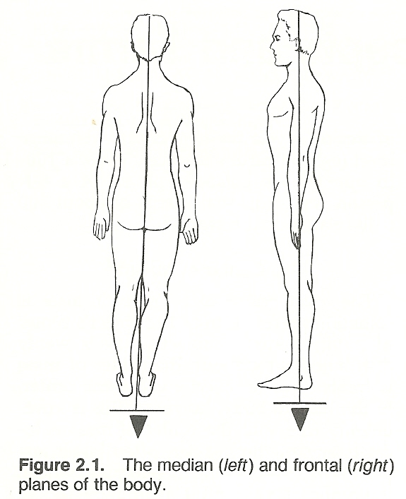
The term weight is not synonymous with the word mass. Body weight refers to the pull of gravity on body mass. Mass is the quotient obtained by dividing the weight of a body by the acceleration due to gravity (32 ft/sec524). Each of these terms has a different unit of measurement. Weight is measured in pounds or kilograms, while mass is measured by a body's weight divided by the gravitational constant. The potential energy of gravity can be simply visualized as an invisible spring attached between the body's center of mass and the center of the earth. The pull is always straight downward so that more work is required to move the body upward than horizontally (Fig. 2.1).
Newton's Laws of MechanicsSir Isaac Newton's three laws of mechanics apply in any movement or injury and serve as the basis for the science of mechanical engineering. They are applied throughout the study of biomechanics and deserve definition and explanation.
The Law of Inertia
NEWTON'S FIRST LAW
A body remains at rest or in a state of uniform motion in a straight line until acted upon by an unbalanced or outside force. When a body is at rest, the forces acting upon it are completely balanced. When the body or a part is in motion, it will continue to move until some force causes it to stop. All objects express inertia in that they resist change whether at rest or in motion. The force necessary to overcome the inertia of a body depends upon the weight of the body and the rate at which it is moving. It is for this reason that more effort is required to put a shot than throw a baseball the same distance.
An object does not move unless a force has been applied that is greater than the object's inertia. A body at rest may have many forces acting upon it; and if their magnitudes and directions completely cancel one another, there is zero net force and a state of static equilibrium. If these forces are unbalanced and result in a net force other than zero, movement (dynamics) occurs.
The Law of Acceleration
NEWTON'S SECOND LAW (PROPORTIONALITY)
The acceleration of an object is proportional to the unbalanced forces acting upon it and inversely proportional to the object's mass. In other words, the net force acting on a body gives it an acceleration that is proportional to the force in both direction and magnitude and inversely proportional to the mass of the body.
ACCELERATION MEASUREMENT
A forceful push moves a small object rapidly; a light push on a large object moves it slowly. Acceleration is a quantity, where changes in direction or magnitude may occur, which refers to the rate of change of linear velocity. It is measured by its magnitude in feet or meters per second per second. Mathematically, acceleration = force/mass, or final velocity minus original velocity divided by time.
The Law of Reaction
NEWTON'S THIRD LAW (INTERACTION)
For every action there is an equal and opposite reciprocal reaction. Inertia is manifest as a reaction equal and opposite to the action that created the acceleration. Thus, forces are always in pairs that are equal in magnitude but opposite in direction. It is arbitrary which force is called the action and which the reaction, but usually in biomechanics we refer to internal body forces as actions and external forces applied to the body as reactions (eg, weights, floor reactions).
EXAMPLES OF REACTION
Regardless what degree of force is induced upon a part, there is always a counteracting stress because for every action there must be a reaction. For instance, a downward pressure equals an opposing upward thrust (eg, as that of a rocket). When an individual pushes against or lifts up any object, the object pushes against the person or pulls down with equal force in a line directly opposite to that of the individual's force. A force pulling right is equal to a pull toward the left, expressed in terms of centripetal and centrifugal force. A spiraling force in one direction must be accompanied by an equal twisting force in the opposite direction. A force permitting a part to slide downward must be resisted by an adequate upward force. And a force tending to bend a structure along its axis must be resisted by a force equal to prevent such bending.
ForceForce, simply, is any push or pull produced by one object acting upon another. It is anything that tends to cause or change the yield movement acceleration of an object. For example, when an object at rest is pushed (or pulled), it moves in the direction of the push at a speed relative to the strength and time of the pushing force. Linear movement without turning is called translation, and it is the result of the force passing through the center of mass. Some degree of rotation will accompany translation if the line of push or pull does not pass through the center of mass. The further the line of force is from the center of mass, the greater is the rotational component.
Force is measured in gravitational units: pounds or kilograms. It has two components: strength (magnitude of force) and direction.
Moments
The term moment in mechanics refers to the tendency, or measure of tendency, to produce motion, especially about a point or axis. The moment of inertia is greatest in all axes of the body that go through the center of gravity of the body, and it is less through axes which pass outside this center of gravity. Thus, it is easier to topple an upright object by striking it high or low than in the midsection.
It is easier to spin a person around by striking his outstretched arm than by striking his shoulder. When a force produces rotation, the measure of this rotational effect is called a moment of force or torque. The rotation moment of such a force can be computed by the force applied times the perpendicular distance from the center of rotation.
Types of Force
LOAD AND STRESS
Forces and or moment (torque) external to a particular structure such as gravity, another muscle contraction, inertia, wind, water resistance, and surface reaction are referred to as loads. The applied weight used in traction or an adjustment and the resistance offered to an exercise are external mechanical loads. Interior resistance forces such as tendon tensile strength and muscle stretch which react to a load are referred to as biomechanical stress.
NEWTONS
Loads are often measured by newtons, the universal measure of force based on Newton's second law of motion. A newton (N) is the quantity of force necessary to give a 1-kg mass an acceleration of 1 meter per second per second: 1 N = 0.2248 poundforce; 1 poundforce = 4.48 newtons. Note that, unlike pounds and kilograms, a newton's definition does not depend on the earth's gravitational field.
SUBSTANCE MECHANICAL PROPERTIES
The mechanical properties of a substance determine how it will react to load and stress. If a substance's mechanical properties are identical in all directions such as a metal, it is isotropic. A sample portion of an isotrophic material shows the same characteristics of strength and elasticity as any other sample portion. As every human tissue is specialized to resist customary loads, the human body contains no isotropic structures.
All body tissue is anisotropic; ie, its mechanical properties differ with varying area orientations. As an example, a bone will vary in its strength and elasticity to a load depending upon whether the load is applied transversely, axially, at an angle, or with a twist.
External Loads
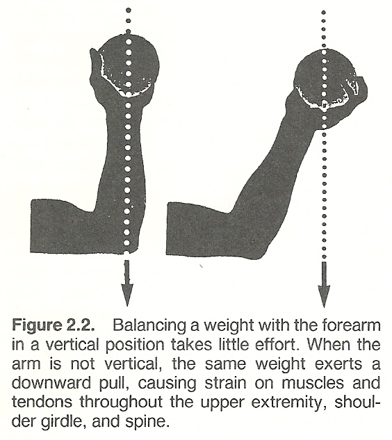
The resistance offered to the forces of musculoskeletal structures and joints is commonly derived from gravitational pull, the resistance of a fixed structure, manual resistance, environmental factors (eg, swimming in water, running against wind), elasticity, and friction factors. Gravity is the most common external force to which the body is subjected, and it always offers a force directed in a straight line downward. In determining the effect of gravity, the weight and position of resistance must be considered (Fig. 2.2).
SAMPLE CLINICAL APPLICATIONS
Such factors have common applications in therapeutics. When the resistance of gravity is not desired (eg, in weakness), the resistance of the body can be reduced by immersion in water where the body is buoyed up by a force equal to the weight of the water displaced to balance the gravitational force on the body. Canes and crutches also help to reduce gravitational forces on a weak or tender body part.
When resistance is desired, stationary or resistant structures and manual loads are utilized in developing isometric muscle contraction. In therapeutic exercise, for instance, friction devices to offer load resistance against muscle contraction are popular. A variety of elastic materials are used such as springs and tubes where the line of resistance lies along the length of the elastic material.
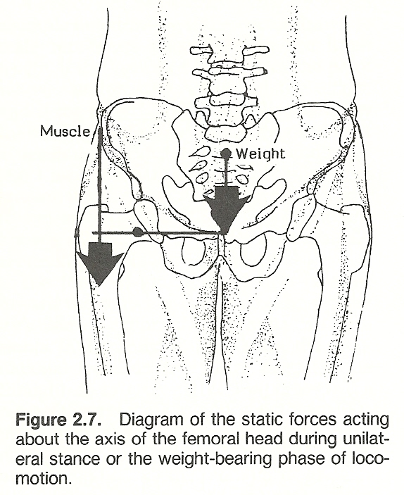
STRESS ON WEIGHT-BEARING JOINTS
Hollingshead/Jenkins point out that the pull of supporting muscles frequently increases joint pressure in weight-bearing joints. For example, if a 200-lb person leans so that his weight is supported on one limb, the hip joint is subjected to all the person's weight above the hip, plus the weight of the other limb, and it also withstands the pull of the muscles necessary to maintain equilibrium. As one lower limb is typically 15% of total body weight, this would mean the support of 170 lb of body weight plus 425 lb of balance force for a total force on the hip of almost 600 lb. This happens during quiet standing; running or holding a weight would greatly add to the stress.
SPINAL LOAD CONSIDERATIONS
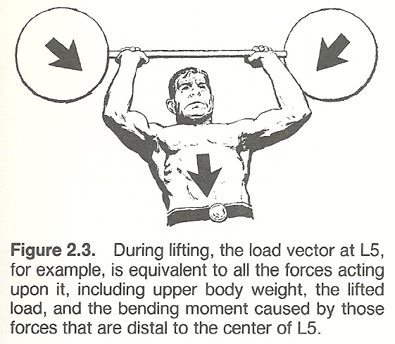
Typical spinal loads offer another example of the effects of external forces on the musculoskeletal system. When the spine is loaded in lifting a weight, the lumbosacral area is subjected to weight forces from both the upper body plus the weight being lifted. It is also being subjected to the bending torque caused by these forces because they are some distance from L5's center of mass. The load on the lumbosacral disc is the sum of the weight of the upper body, the weight held, the spinal muscle forces, and their lever arms respective to the disc.
The importance of spinal loads is underscored in such activities as lifting, bowling, rowing, and even in lordotic joggers. It has been estimated that when an object is held 14 inches away from the spine, the load on the lumbosacral disc is 15 times the weight lifted. Thus, a mother lifting a 20-lb child at arms' length theoretically places a 300-lb load on her lumbosacral disc.
Another example is a dead lift of 200 lb by a 170-lb person where it has been shown that a 2000-lb force is exerted on the lumbosacral disc (Fig. 2.3). This load, of course, must be dissipated, otherwise the L5 vertebra would be crushed. The load is dissipated through the paraspinal muscles and, importantly, by the abdominal cavity which acts as a hydraulic chamber to absorb and thus diminish the load applied.
These observations on spine loading emphasize the vulnerability of the spine to the mechanical stresses placed upon it, especially in people with poor muscle tone. Bony compression of the emerging nerve roots arises as a result of subarticular entrapment, pedicular kinking, or foraminal impingement due to posterior vertebral subluxation.
STRESS ON NONWEIGHT-BEARING JOINTS
Even joints that do not bear weight can be subjected to tremendous pressure. For example, when the extended forearm is flexed, the flexors exert a line of pull that is almost parallel to the the ulnar and radius. Thus, much of the muscular force is exerted at the elbow joint which compresses the articular surfaces. Because of the lack of complete articular reciprocity, this pressure isconcentrated onto an area far less than that of the whole apposed articular faces. If the hand holds a weight during this flexion, the contraction must be of greater force, which in turn causes greater pressure.
OTHER FACTORS
The total stress on the body during lifting is not completely determined by mechanical factors, however. It has been found that the combined effect of biomechanical and physiologic stresses leads to an overall measure of lifting- task acceptability as expressed by the psychophysical stress involved. One study has found that there are conditions for which the acceptability measures of the combined biomechanical and physiologic stresses and the psychophysical stresses involved were close to one another. (41)
The Characteristics of Force
The four features of a force are its magnitude, action line, direction, and point of application. A force cannot be described unless these factors are known because any variation of one or more of these factors changes the result.
MAGNITUDE AND ACTION LINE
Magnitude is a scalar quantity such as time, speed, temperature, volume, and length that has no direction. More factors must be known besides magnitude if a force involving a stress is to be accurately described. For example, a 5-lb weight held in a hand when the arm is held vertically produces a far different effect in the shoulder joint than the same weight held in the hand when the arm is held horizontally. Thus, the action line (line of force application) must be known.
DIRECTION AND POINT OF APPLICATION
Since a pulling force has a different effect than a pushing force, it is important to know the direction of force along the action line. In addition, the site where the force is applied must be known to complete the picture.
Biomechanical Descriptions
Many basic considerations in biomechanics involve time, mass, center of mass, movement, force, and gravity --all of which operate in accordance with the laws of physics. However, while numerous parameters of movement are interrelated, no one factor is capable of completely describing movement by itself. For example, acceleration and velocity involve displacement and time, but they are insufficient unless force and movement are considered.
VECTORS
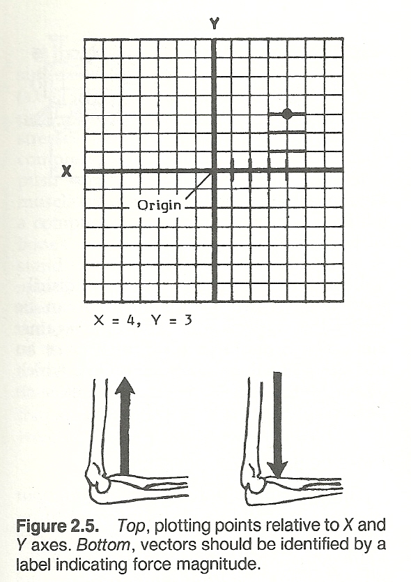
Although force is usually applied over an area, it is usually described in biomechanical drawings as a summarized point force by an arrow. Any quantity that gives both magnitude and direction is a vector (eg, a force) that can be described by a straight line. Quantities that involve only magnitude are referred to as scalars. When illustrating a force, the vector's length should be proportional to the magnitude of the force. For example, if 1 inch is used to represent a 10-lb force, a 2-inch line would represent a 20-lb force.
A vector can be used to define a force in a simple line drawing if the vector drawn to scale represents magnitude by the line's length, if the vector's tail indicates the point where the force is applied on the object, and if the direction of force is indicated by the vector's arrowhead. If the magnitude of a vector is known, it should be indicated (eg, 1 inch = 20 lb). If the magnitude is not known, it is indicated by the capital letter F (force) or P (pressure) to designate the unknown magnitude. Distances are usually represented by lower case letters.
The force of gravity is always directed toward the center of the earth. Thus, gravity's line of action and direction are constants. In the upright "rigid" body, the gravitational force on the entire mass can be thought of as a single vector through the center of mass which represents the sum of many parallel positive and negative coordinates (Fig. 2.4). If a weight is held in the outstretched hand, the quantity of gravitational force is governed by the weight of the extremity plus the weight held.
SPACE
As a force may act along a single line in a single plane or in any direction in space, this must be considered to provide an illustrative reference system. In a two-dimensional system, the plane is simply divided into four quadrants by means of a perpendicular vertical ordinate line (Y axis) and a horizontal abscissa line (X axis). The point of axial intersection is referred to as the system's origin (Fig. 2.5). Abscissa (X) measurements to the right of the origin are considered positive, while those to the left are negative. Ordinate (Y) measurements above the origin are considered positive, while those below the origin are negative. By this method, any point on the plane can be given an X and Y value.
The term coordinates refers to specific point locations from the origin which have been given a value. For example, a point located 5 units to the right of origin and 3 units down from the origin would be defined as X = 5, Y = 3.
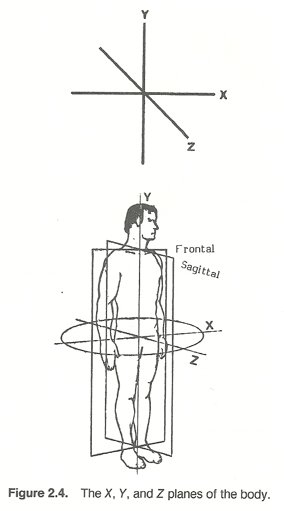
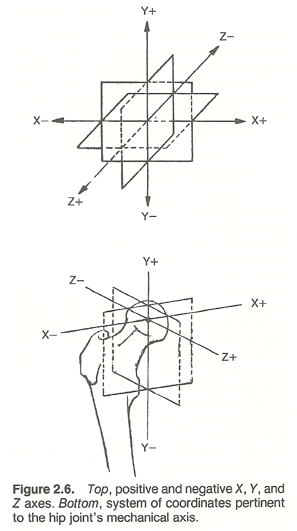
A third axis (usually titled Z) can be introduced to locate points in three dimensions. Such an axis crosses the origin and is perpendicular to the other two planes (X and Y). All Z points in front of the X-Y plane are positive, while those behind are negative (Fig. 2.6). By utilizing X, Y, and Z coordinates, any point in space can be located and depicted. However, a minimum of six coordinates is necessary to specify the position of a rigid body. Force and moment are three dimensional vectors having three components each; thus load may be considered a six-component vector.
In biomechanics, the body's origin is located at the body's center of mass which is usually just anterior to the S2 segment. When this point is known, gross body space can be visualized as being in the sagittal (right-left) Y-Z plane, frontal or coronal (anterior-posterior) X-Y plane, or horizontal or transverse (superior-inferior) X-Z plane. With such a reference system, any movement of any body segment in these planes can be approximately described by placing a coordinate system at the axis of a joint and projecting the action lines of the muscles involved.
Equilibrium
While forces of all types may cause subluxations, dislocations, fractures, strains and sprains, etc, the biomechanical mechanisms involved determine the type and extent of the injury produced depending upon the applications of force and its resistance. For example, different applications of force may cause bending, stress, or compression fractures. When the examiner understands how an injury was caused, the tissues involved are more readily located and the extent of injury is more quickly ascertained.
Following is a brief discussion of linear, concurrent, and parallel forces, and their effect upon equilibrium. However, forces acting on a body are sometimes neither linear, concurrent, or parallel. General forces always include at least four forces to maintain equilibrium.
Linear ForcesLinear forces are those acting in the same straight line (Fig. 2.8). If two forces are to be in equilibrium in a linear system, the forces must be equal in magnitude and exactly opposite in direction.
Pressure
Pressure refers to how a force is distributed over a surface. Pressure (P) can be defined as the action of a force (F) against some opposing force distributed over an area (A) as in the equation P = F/A, which gives the units of force per unit area such as in pounds per square inch (psi).
PRESSURE DURING MANIPULATION
This principle of force is used throughout therapy. In manual adjustment procedures, for example, a patient can withstand a broad palm contact with considerable force without discomfort, yet the same force exerted by a thumbtip or pisiform contact becomes quite painful because the pressure per unit of surface area is now much greater. Thus, whenever pain or skin damage is the priority consideration, the contact forces should be applied over as large an area as possible.
PRESSURE OF SUPPORTS
The same principle must be applied in taping procedures to avoid circulatory and neural impairment, in applying traction slings to distribute force, and in fitting supports if pressure sores are to be avoided. The noxious effects of continuous pressure can be reduced by using somewhat elastic materials such as felt or foam rubber padding as an underlay beneath supports to spread force from prominent bony areas. In large-area supports such as for scoliosis, an underlying water-inflated football bladder has shown to offer automatic pressure distribution and good reciprocity to surface shape. The modern use of air splints during transportation of extremity fractures is another example of this principle applied in health care.
Compression
A pressure always results in a compression stress. Tensile and compression stresses (axial stresses) operate along the axis of a part without altering it. Both of these stresses are measured in newtons. A compression force within the body tends to push substances closer together. When a muscle crossing a joint contracts, it produces a compression force into the joint, and the bones must produce a reactive force to withstand the compression force. Within the spine, the vertebrae and the intervertebral discs are the major compression-carrying components which must support the weight of the body above a particular disc, the initial tension in other ligaments, the additional tension in the muscles and ligaments that are necessary to balance eccentric trunk weight, plus any added external load.
Tension
A pull causes a tensile stress that is an action directly opposed to compression. When tension is applied to connective tissue fibers, the fibers elongate to their physiologic limit somewhat like a stretched rubber band unless a cut or weakness produces a fracture. During torsion (shear) stress, fibers at 45* to the long axis are placed in tension. When a long structure is subjected to bending stress, tension is exhibited in the fibers on the convex side of the curvature.
MOTION TENSION
Examples of tension are exhibited during all spinal movements. Anulus fibers of the intervertebral discs are placed in tension during disc torsion when the spine is rotated axially, and ligaments posterior to the instantaneous axis of rotation are tensed during spinal flexion. A spinal curvature in any direction involves a constant state of abnormal tension and compression of bones, cartilages, and muscles.
During work, muscles do not maintain a constant tension, length, or move with a constant rate of shortening. The strength of muscle action is affected markedly by the amount of tension in the muscle at the start of movement, the degree of muscle stretch at the beginning of contraction, and the rate at which shortening takes place.
POISSON'S RATIO
Similar to a piece of rubber, elastic connective tissue fibers thin during stretch and thicken during compression. In both cases, however, the volume remains constant. The ratio between axial strain in length from compression to transverse strain in diameter from tension is Poisson's ratio.
Concurrent ForcesIn a concurrent force system, as contrasted to a linear system, the forces acting on the body meet at a certain point rather than lie along the same line of action. These forces may be applied to the body from different angles so that their action lines cross either interior or exterior to the body (Fig. 2.9). For example, if two coplanar nonparallel muscles are acting on a bone, a third concurrent force, passing through the point of intersection of the two original muscle forces, must act to maintain equilibrium and avoid rotation.
Parallel ForcesWhen parallel forces some distance from each other act upon a body, their forces must be completely nullified by each other if the body is to maintain equilibrium. If forces do not coincide at the same point, such as in a concurrent system, the result is rotation around a stationary axis. A simple form of this action is a force system where the forces lying in the same plane are parallel. Any force acting on an object at a distance from a fixed point tends to rotate the object. Forces producing clockwise rotation are arbitrarily referred to as positive, while counterclockwise forces are termed negative.
The distance from the point of force application (pivot point) to the point of rotation is called the moment arm or lever arm. When a force acts at a dis- tance from a pivot point, its effectiveness is determined by both its magnitude and its location.
The tendency of a force to cause rotation about an axis that is equal to the magnitude of the force times the perpendicular distance from the action line of the force to that point is referred to as a moment (torque) of force. Mathematically, it is expressed as moment = force X distance, and its unit of measure is in foot-pounds (ft-lb), kilogram-centimeters (kg-cm), or an equivalent measure.
Lever Actions
A lever system is a good example of moments developed by coplanar forces. Simply, a lever is a rigid bar turning about an axis. The three components of a lever are the fulcrum upon which the lever turns, the resistance or weight load which is to be moved, and the effort which moves the lever.
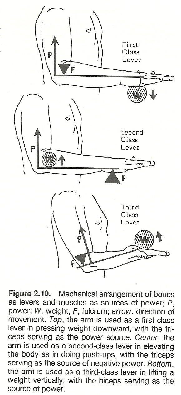
The articulating surfaces of joints are usually used as fulcrums, the rigid bone shafts extending from axis to axis serve as lever arms, and the source of effort to move the lever arms are the muscles. That is, in the body, we have an effort force and a resisting force acting around a pivot axis (fulcrum) which serves as a supporting force (Fig. 2.10). When a muscle contracts, the bony lever arm to which it is fixed is pivoted about the fulcrum. Work is done when resistance is overcome by a lever system. Here again is an example that the resistance to be overcome by the body is generally the sum of the load of the lever segment plus the load of the object to be moved.
MECHANICAL ADVANTAGE
The force developed when a muscle contracts is determined by the mechanical advantage of the levers employed. The position of the attachment of the muscle in relation to the position of the center of the resistance and the position of the fulcrum are important in deciding the mechanical advantage of any lever. Mechanical advantage is the ratio of output force delivered to the input force applied by a mover. If the resistance is placed near the fulcrum, the mechanical advantage is good. If the same resistance is placed further from the fulcrum, the mechanical advantage lessens and a greater effort is required to overcome the resistance.
Mechanical advantage is computed by dividing force into resistance: R/F. If a 150-lb individual wishes to lift a 1200-lb weight by means of a lever, the mechanical advantage required of the lever would be R/F = 1200/150 = 8. Thus, the force arm must be eight times as long as the resistance arm of the lever.
TYPES OF LEVERS
At one time or another, every bone in the body, acting alone or in combination, acts as a lever, and the human machine offers many examples of first- and third-class levers. Most of the joints of the body can be used as levers of more than one class.
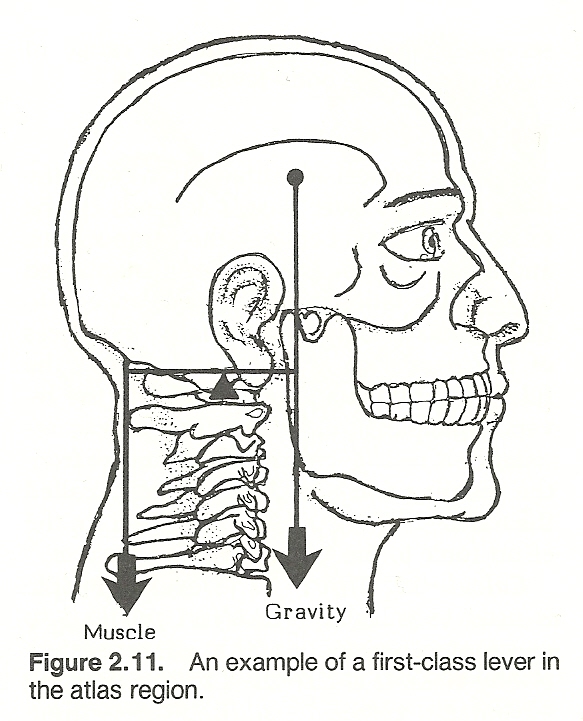
First-Class Levers. An example of a first-class lever where the fulcrum is located between the applied load and the resisting weight is seen in tapping the toes on the floor and in the action of the triceps on the ulnar when the arm is held over the head. Other examples are found (1) when the spleni act to extend the skull across the atlanto-occipital joints (Fig. 2.11) and (2) when the soleus tendon force behind and the gravity force in front of the ankle fulcrum are utilized in standing erect. In a first-class lever system, the longer the lever arm, the less force is required to move or resist the applied load.
Second-Class Levers. A second-class lever has the resistance weight located between the applied force and the fulcrum. Since most of the muscles moving each joint are inserted near the joint and the resistance is usually at the long end of the body levers, levers of the first and third classes are the most commonly used in the body. There are no positive second-class levers in the body because the length of the resistance arm of the movement is always greater than that of the effort arm when movement is produced by muscle shortening. Some kinesiolo- gists refer only superficially to the action of the brachioradialis on the forearm during elbow flexion and the action of the calf plantar flexors when one stands on the toes as being second-class lever actions. A true second-class lever system can be demonstrated, however, when muscle tension becomes a resistance to a reversal of joint action caused by an outside force so that a third- class lever system is reversed and becomes a second-class lever system. In such cases, the eccentric muscular contraction is performing negative rather than positive work. An example of this is seen when one stands on tiptoes where the fulcrum is located on the ball of the foot, and force is applied through the gastrocnemius at the ankle to lift body weight.
Third-Class Levers. A third-class lever, where the applied force is always located between the fulcrum and the supported weight (resistance), is seen in the action of the biceps in flexing the forearm. The biceps inserts between the elbow and the hand; thus, when the biceps contracts, the elbow joint serves as a fulcrum. The same mechanism is seen in lifting a weight with the foot.The resolution of the force of gravity or muscle contraction into components must include a rotary component. Also, the distance from the point of application of the rotary component to the axis of motion in the joint must be consid- ered. The joints which serve as fulcrums also limit the range of movement of the body lever.
THE LEVERS PRINCIPLE
The mechanical advantage derived by the three different lever classes depend on the relative distances between the components, and the levers principle has been established upon this relationship. The resistance is to the effort inversely as the relative distances of the resistance and the effort from the fulcrum. The equation representing the levers principle is: effort X effort arm = resistance X resistance arm. The distance from the resisting force to the fulcrum is called the resistance arm, while the distance from the effort force to the fulcrum is the force arm.Calculating Effort. The levers principle is used to calculate the effort required to overcome a resistance within a lever system of any class. It is also used to calculate the advantages gained by shifting the position of the resistance, the point of application of effort, and the position of the fulcrum. In the body, the points of application of effort and the position of the fulcrums are somewhat fixed by the anatomic location of the origin or insertion of the muscles in relation to the joints. In some instances, however, changes of posture make effective improvements in mechanical advanatge due to shifts in position of the point of application of force and the position of the fulcrum.
Muscle Force. In the musculoskeletal system, all muscle moment arms are short in proportion to the bony levers they move. The moment arm of the muscle is the perpendicular distance from the muscle's action line of force to the axis of the joint involved. This distance must be used to calculate muscle force rather than the length of the lever arm (distance from the muscle's point of attachment from the joint axis).
Human Potential vs Stability. Each year we see athletic performance draw closer to the limits of human capacity. Understanding the biomechanical principles involved helps us to prevent injury and restore functional integrity. While our lever-like extremities transmit forces and motion at a distance, they also favor musculoskeletal injuries by amplifying forces (usually external, occasionally internal) acting on the body's biomechanical system. Statistics indicate that excessive stress appears greatest on the short arm of first-class levers (eg, elbow, knee).
LINEAR AND ANGULAR VELOCITY RELATIONSHIPS
The linear velocity of an object at the end of a lever is the product of the lever's length and angular velocity. Thus, an increase in angular velocity and lever length increases the linear velocity because the end of the lever travels further per unit of time. In addition to a longer lever's increased velocity, it takes greater force to move it because the torque exerted by an object at the end of the lever is the product of the length of the lever and its weight.
Wheel and Axial Mechanisms
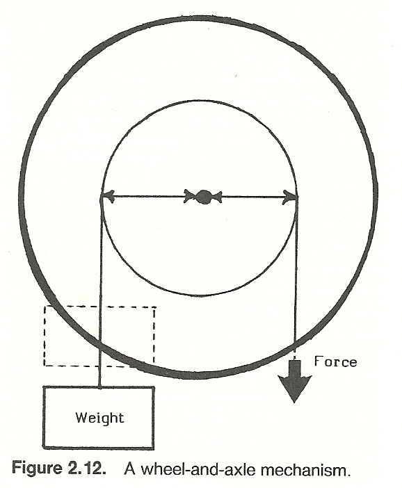
The wheel-and-axle machine, consisting of a wheel attached to a central axle about which it revolves, works on the lever principle (Fig. 2.12). Rotational force may be applied to either the rim (eg, a steering wheel) or axle (eg, a drive shaft).
Numerous examples of such mechanisms are found within the human machine. For instance, all joint rotation movements in the body involve such a mechanism. On cross section, one readily sees that a long bone of an extremity serves as an axle and its surrounding muscles as a wheel. In the thorax, the rib cage serves as a wheel and the spine as the axle. Here, force is applied to the ribs by the oblique abdominal muscles and to the vertebrae by the deep spinal muscles.
Pulley Systems
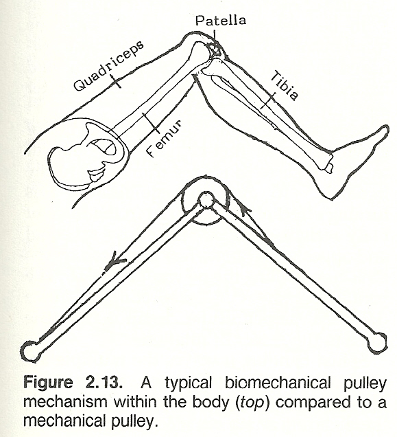
A pulley system may be constructed as either a linear or concurrent force system. A pulley functions as that of a first-class lever with equal arms. Within the body, various fixed pulley systems that may act in any direction are utilized to alter the angle of action on the body by providing resistance, stabilization, and/or to assist movement (Fig. 2.13).
An example of a fixed single pulley in the body is the patella. The position of the patella changes the direction of quadriceps pull on the tibial tuberosity so as to increase the mechanical advantage. Another example can be found in how the external malleolus of the ankle serves to change the pull of the peroneus longus muscle.
Force Couples
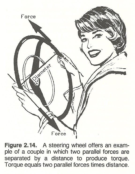
A mechanical couple represents a special case of a pair of parallel forces of equal magnitude that act in opposite directions some distance apart and tend to produce rotation (Fig. 2.14). Two non-colinear parallel forces that are equal in magnitude and opposite in direction have a net force that is zero. While no linear motion would occur in the body, these forces, representing a couple, produce a rotation effect on the body. The torque (T) of a couple is expressed mathematically as T = force in newtons X perpendicular distance in meters. Pure rotation cannot take place unless there is a couple.
TYPICAL APPLICATIONS
Examples of muscle actions that have a couple-like action are exhibited in anterior pelvic tilting by contraction of the lumbar extensors and hip flexors, thoracic rotation on the pelvis by contraction of the latissimus dorsi and contralateral external oblique muscles, and rotation of the head about the axis between C1 and C2 by contraction of the splenius capitis and contralateral sternocleidomastoideus muscles. Scapulohumeral rhythm and the depression action of the rotator cuff muscles on the humerus are two other examples of couple mecha- nisms. An interruption in either of these two couples compromises shoulder girdle motion. Typical side-position lumbar and pelvic adjustments and cervical rotatory adjustments incorporate twisting forces to the spine in opposite directions by action of the adjustor's stabilizing and contact points.
A couple consisting of small forces with a large distance between them is just as effective in producing rotation as one where the forces are great and the distance between them is small. For example, in a rotatory adjustment, a lesser force is necessary to produce the same effect when contact is taken well on a transverse process than one taken closer to the spinous process.
COUPLING
A coupling is a device that serves to connect the ends of adjacent parts of objects to produce a phenomenon of consistent association of one motion about an axis with another simultaneous motion about a second axis. In the spine, for example, axial rotation is coupled with lateral bending, vertebral anterior translation is coupled with flexion rotation, lateral scoliotic deformity is coupled with axial rotation to rotate the posterior vertebral elements toward the concavity of the curvature, and vertebral movements toward and from the sagittal plane are coupled with associated rotatory and translatory movements.
Bending
If a load is applied to a relatively long structure that is not directly supported at the point where the load is applied, the resulting deformity is called bending. During bending, the fibers on the concave side of a connectivetissue structure are compressed, while those on the convex side are stretched.
Two effects are seen when a force acts on an object. First, the object tends to move in the direction that the force is applied (translation). Second, the force will cause the object to rotate (bending moment).
BENDING MOMENT
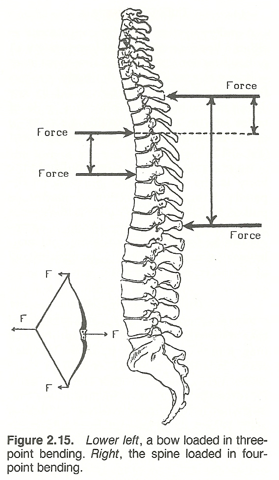
A bending moment (torque) is a quantity, usually measured in newton meters, at a point in a structure that is equal to the product of the applied force and the shortest distance from the point to the force direction (Fig. 2.15). For example, think of the trunk of a person sitting as a tree trunk and a laterally abducted arm as a branch of the tree. If a heavy book is placed on an out- stretched hand, the bending moment increases in magnitude from zero at the hand to the maximum at the junction of the tree trunk and branch (shoulder). In the same manner, relatively small weights placed on horizontal limbs apply substantial bending moment at the thoracic and lumbar discs because of the long lever arm. If equilibrium is to be maintained, this stress must be compensated by the bending moment produced by large magnitudes of muscle and ligament force because of the much shorter lever arms of these tissues.
Body weight acting through the center of gravity and the first class lever sytem of the hip tends to rotate the trunk toward the midline. To maintain equilibrium, this turning effect about the hip from the force of body weight must be resisted by an equal and opposite turning effect produced by the abductors pulling the pelvis downward. The bending moment is the product of force times the perpendicular distance from the force to the center of rotation.
Spinal bending involves the multiple actions of tension, compression, and torsion. The amount of this fiber stress (S) equals the bending moment (B) divided by the sectional moment (I) of inertia times the fiber distance from the neutral axis (Y): S = B/I X Y. If the radius (R) of the curvature is desired, it may be computed by R = E/B X I, where E is the modulus of elasticity of the material.
The moment of inertia of an elliptical object is greatest for bending loads in the direction that is parallel to its major axis. For this reason, the elliptical cross section of a vertebra's pedicle is seen to be most suitable for taking up bending loads in the sagittal plane where such loads are common.
MULTIPOINT BENDING
Both three-point and four-point bending occur within the body. Three-point bending is a form of bending where one force is applied to one side of a structure and two forces are applied on the other side. Examples are seen with a seesaw or a drawn bow string. In four-point bending, two transverse forces are applied on one side of a structure and two are applied on the other. If the forces are equal and symetrical, the structure between the inner two forces is constantly subjected to bending moment.
THE NEUTRAL AXIS
When a long fibrous structure is subjected to bending, the longitudinal line where normal axial stress is zero is referred to as the neutral axis (Fig. 2.16). The plane of the neutral axis is that area situated between the fibers under tension on the convex side of the curvature and the compressed fibers on the concave side. However, there is usually shear stress along the neutral axis resulting from transverse forces even though the tension-compression stress is zero. In cases of torsion stress applied about the neutral axis, the fibers at the neutral axis will have zero shear stress.
Torsion
The mechanical internal moment or couple of restitution which arises in a cord or rod when twisted is referred to as torsion (Fig. 2.17). That is, torsion or torque is the load that is applied by force couples about the long axis of a structure. The moment of torque is the product of a force and its perpendicular distance from the fulcrum. Thus, torque (T) is synonymous with force (F) times the length of the lever arm (a): T = Fa.
If the torques on either side of the fulcrum are equal, the lever is in equilibrium. As mentioned previously, when a lever is in equilibrium, the sum of the moments of force or torques tending to turn it in one direction (eg, clockwise) about a given point must equal the sum of the moments of the torques tending to turn it in the opposite direction (counterclockwise) about the same point.
APPLICATION PRINCIPLES
Practically all muscles pull obliquely and some pull with a slight twist. The oblique insertion of the pectoralis major into the humerus, for example, causes the humerus to be rotated as well as adducted during contraction of the muscle. In addition, all angles of pull against the bones change with each fraction of a degree of movement. For instance, the angle of pull of the biceps upon the radius changes with each degree of flexion of the elbow.
If torque is applied to the ends of a curved structure, each cross section of the structure is subjected to both torsion and bending forces. Many researchers feel that this principle is responsible for the low-back pain from disc failure because simple axial rotation of the trunk (load) produces severe torsion and bending stress on the lumbosacral disc.
When considering rotational movement, torque fills the same role that force does for motion in a straight line. That is, the magnitude of the moment increases or decreases the angular velocity of an object to produce acceleration or deceleration of the rotation involved.
TORSION TERMSTorsional Rigidity. Rotatory stiffness is called torsional rigidity in mechanics and represents the torque per unit, measured in newton meters per ra- dian, of angular deformation. This rotatory stiffness is a characteristic of all body joints.
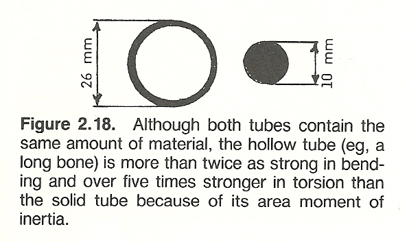
Area Moment of Inertia. According to Newton's first law, the terms mass and inertia can be used interchangeably. The term "moment of inertia" describes the degree to which a material's shape influences its strength. There are two types: area and polar. The area moment of inertia refers to a measure, in feet or meters to the fourth power, of the distribution of material about its center which determines its bending and torsion strength (ie, its bending resistance). It is for this factor that a hollow tube such as a long bone is many times stronger in bending and torsion than a solid tube of identical mass (Fig. 2.18).
Polar Moment of Inertia. This is that characteristic of the transverse sec- tion of a long object that gives a measure of the distribution of the substance about its axis to increase its torsional strength (resistance). It is also measured in feet or meters to the fourth power. The greater distance a mass is from its axis of torsion, the greater its polar moment of inertia. The reason that the tibia spiral fractures most frequently at the junction of its middle and distal third is because this site has a low polar moment of inertia, even though the cortex is especially thick at this point.
Shear Stress. A force directed against a structure at an angle to its axis that permits one part to slide over the other is called a shearing stress. Typical examples are that of the cervical and thoracic vertebral articular facets and that occurring at the intervertebral disc and vertebral body junction. In shear stress, both articulating parts may be movable with the parts sliding in opposite directions or one part fixed. Shear stress represents the intensity of force parallel to the surface upon which it acts and is measured in newtons/meter524 or pascals. Because bone is weaker in tension than in shear, torsional overstress produces spiral fractures in long bones.
Shear Modulus. Shear modulus is a material property that represents the ratio of a substance's shear stress to its shear strain. As is shear stress, it is measured in newtons/meter524. Materials such as rubber and ligamentous tissue with their low modulus of elasticity also have a lower, about 38% lower, modulus of shear.With these concepts and terms in mind, we shall be able to proceed to those of dynamics and stability.
************************************************************** Chapter 2 References:
- Williams JGP, Sperryn PN (eds):
Sports Medicine, ed 2.
Baltimore, Williams & Wilkins, 1976, pp 119123
- Alley PW, Sells RL:
Introduction to Physics.
Boston, Allyn & Bacon, 1971
- Madley R, Winter R:
Modern Physics: A Student Study Guide.
New York, John Wiley & Sons, 1971
- Wilkie DR:
Man as a source of mechanical power.
Ergonomics, 3(1), 1960
- Barham JN, Wooten EP:
Structural Kinesiology.
New York, Macmillan, 1973, pp 8586
- Clauser CE, et al:
Weight, Volume, and Center of Mass of Segments of the Human Body,
Wright-Patterson Air Force Base, Ohio, AMRL-TR6970, 1969
- Dumbleton JH, Black J:
Principles of mechanics. In Black J, Dumbleton JH (eds): Clinical Biomechanics: Case History Approach.
New York, Churchill Livingstone, 1981, pp 367-368
- Clauser CE, McConville JT, Young JW:
Weight, volume, and center of mass of segments of the human body.
AMRL-TR6970, Wright-Patterson Air Force Base, Ohio, 1969
- Schenck JM, Cordova FD:
Introductory Biomechanics, ed 2.
Philadelphia. F.A. Davis, 1980, pp 17.
- Kendall HO, Kendall FP, Wadsworth GE:
Muscles: Testing and Function, ed 2.
Baltimore, Williams & Wilkins, 1971, p 18.
- Squire PJ:
Centre of gravity height and its relation to anthropometric measurements in female physical education students.
Journal of Human Movements Studies, 3:214220, 1977.
- Cochran GVB:
A Primer of Orthopaedic Biomechanics.
New York, Churchill Livingstone, 1982, pp 1415.
- Barham JN, Wooten EP:
Structural Kinesiology.
New York, Macmillan, 1973, pp 87, 129130, 134135.
- Gowitzke BA, Milner M:
Understanding Scientific Basis of Human Movement, ed 2.
Baltimore, Williams & Wilkins, 1980, p 55.
- Williams JGP, Sperryn PN (eds):
Sports Medicine, ed 2.
Baltimore, Williams & Wilkins, 1976, pp 108110.
- LeVeau B: Williams and Lissner:
Biomechanics of Human Motion, ed 2.
Philadelphia, W.B. Saunders, 1977, p 10.
- Barham JN, Wooten EP:
Structural Kinesiology.
New York, Macmillan, 1973, pp 99100.
- Edwards S: Physics:
A Discovery Approach.
New York, John Wiley & Sons, 1971.
- Straley JW:
Basic Physics.
Englewood Cliffs, NJ, Prentice-Hall, 1974.
- Cochran GVB:
A Primer of Orthopaedic Biomechanics.
New York, Churchill Livingstone, 1982, pp 1, 13, 16, 152153.
- Straley JW:
Basic Physics.
Englewood Cliffs, NJ, Prentice-Hall, 1974.
- Barham JN, Wooten EP:
Structural Kinesiology.
New York, Macmillan, 1973, p 131.
- Schenck JM, Cordova FD:
Introductory Biomechanics, ed 2.
Philadelphia. F.A. Davis, 1980, pp 2224.
- LeVeau B: Williams and Lissner:
Biomechanics of Human Motion, ed 2.
Philadelphia, W.B. Saunders, 1977, pp 46.
- Dumbleton JH, Black J:
Principles of mechanics.
In Black J, Dumbleton JH (eds): Clinical Biomechanics: Case History Approach.
New York, Churchill Livingstone, 1981, pp 360364.
- White HE:
Modern College Physics, ed 5.
New York, Van Nostrand Reinhold, 1966.
- Fowler RG, Myer DI:
Physics for Engineers and Scientists.
Boston, Allyn & Bacon, 1958.
- Fuchs WR:
Physics for the Modern Mind.
New York, Macmillan, 1967.
- Schenck JM, Cordova FD:
Introductory Biomechanics, ed 2.
Philadelphia. F.A. Davis, 1980, pp 79, 2526.
- Gowitzke BA, Milner M:
Understanding Scientific Basis of Human Movement, ed 2.
Baltimore, Williams & Wilkins, 1980, p 78.
- Black J, Dumbleton JH (eds):
Clinical Biomechanics: Case History Approach.
New York, Churchill Livingstone, 1981, pp 364365.
- Cochran GVB:
A Primer of Orthopaedic Biomechanics. New York,
Churchill Livingstone, 1982, pp 5, 1217.
- Williams JGP, Sperryn PN (eds):
Sports Medicine, ed 2.
Baltimore, Williams & Wilkins, 1976, pp 107108.
- White AA, Panjabi MM:
Clinical Biomechanics of the Spine.
Philadelphia, J.B. Lippincott, 1978, pp 480481, 457.
- Gonzna ER, Harrington IJ:
Biomechanics of Musculoskeletal Injury.
Baltimore, Williams & Wilkins, 1982, p 12.
- Daniels L, Worthingham C:
Therapeutic Exercise for Body Alignment and Function, ed 2.
Philadelphia, W.B. Saunders, 1977, pp 101102.
- LeVeau B: Williams and Lissner:
Biomechanics of Human Motion, ed 2.
Philadelphia, W.B. Saunders, 1977, pp 12.
- Dumbleton JH, Black J:
Principles of mechanics. In Black J, Dumbleton JH (eds):
Clinical Biomechanics: Case History Approach.
New York, Churchill Livingstone, 1981, pp 360361.
- Hollingshead WH, Jenkins DB:
Functional Anatomy of the Limbs and Back.
Philadelphia, W.B. Saunders, 1981, pp 2829.
- Strait LA, Inman VT, Ralston HJ:
Sample illustrations of physical principles selected from physiology and medicine.
American Journal of Physics, 15:375382, 1947.
- White AA, Panjabi MM:
Clinical Biomechanics of the Spine.
Philadelphia, J.B. Lippincott, 1978, pp 330332.
- Cailliet R:
Low Back Pain Syndrome, ed 3.
Philadelphia, F.A. Davis, 1981, pp 132137.
- Karwowski W:
Fuzzy modelling of stresses in manual lifting tasks.
Ergonomics, 27:641649, 1984.
- LeVeau B: Williams and Lissner:
Biomechanics of Human Motion, ed 2.
Philadelphia, W.B. Saunders, 1977, pp 2332.
- Cochran GVB:
A Primer of Orthopaedic Biomechanics.
New York, Churchill Livingstone, 1982, pp 56, 5458.
- Gowitzke BA, Milner M:
Understanding Scientific Basis of Human Movement, ed 2.
Baltimore, Williams & Wilkins, 1980, pp 4243.
- Barham JN, Wooten EP:
Structural Kinesiology.
New York, Macmillan, 1973, pp 9193.
- White AA III, Panjabi MM:
Spinal kinematics.
In Goldstein M (ed): The Research Status of Spinal Manipulative Therapy,
NINCDS Monograph No. 15, DHEW Publication No. (NIH) 76998, Stock No. 017-049-0 00607,
Washington, DC, U.S. Government Printing Office, 1975, p 93.
- LeVeau B: Williams and Lissner:
Biomechanics of Human Motion, ed 2.
Philadelphia, W.B. Saunders, 1977, pp 67.
- Dumbleton JH, Black J:
Principles of mechanics.
In Black J, Dumbleton JH (eds): Clinical Biomechanics: Case History Approach.
New York, Churchill Livingstone, 1981, pp 359360.
- Barham JN, Wooten EP:
Structural Kinesiology.
New York, Macmillan, 1973, pp 100101.
- Gowitzke BA, Milner M:
Understanding Scientific Basis of Human Movement, ed 2.
Baltimore, Williams & Wilkins, 1980, p 75.
- McCormick WW:
Fundamentals of College Physics.
New York, Macmillan, 1965.
- Shames IH:
Engineering Mechanics--Statics and Dynamics, ed 2.
Englewood Cliffs, NJ, Prentice-Hall, 1967.
- Dempster WT:
Free-body diagrams as an approach to the mechanics of human posture and locomotion.
In Evans FG (ed): Biomechanical Studies of the MusculoskeletaL System.
Springfield, IL, Charles C. Thomas, 1961.
- Dumbleton JH, Black J:
Principles of mechanics.
In Black J, Dumbleton JH (eds): Clinical Biomechanics: Case History Approach.
New York, Churchill Livingstone, 1981, pp 368369.
- White AA, Panjabi MM:
Clinical Biomechanics of the Spine.
Philadelphia, J.B. Lippincott, 1978, pp 476*477,
- Dumbleton JH, Black J:
Principles of mechanics.
In Black J, Dumbleton JH (eds): Clinical Biomechanics: Case History Approach.
New York, Churchill Livingstone, 1981, pp 365-367.
- Schenck JM, Cordova FD:
Introductory Biomechanics, ed 2.
Philadelphia. F.A. Davis, 1980, pp 7681, 85.
- White AA III, Panjabi MM:
Spinal kinematics.
In Goldstein M (ed): The Research Status of Spinal Manipulative Therapy,
NINCDS Monograph No. 15, DHEW Publication No. (NIH) 76998, Stock No. 017-049-0 00607,
Washington, DC, U.S. Government Printing Office, 1975, p 93.
- Sears FW, Zemansky MW:
University Physics, ed 4.
Reading, MA, Addison- Wesley, 1960.
- Halliday D, Resnick R:
Fundamentals of Physics.
New York, John Wiley & Sons, 1974.
- LeVeau B: Williams and Lissner:
Biomechanics of Human Motion, ed 2.
Philadelphia, W.B. Saunders, 1977, p 9.
- White AA, Panjabi MM:
Clinical Biomechanics of the Spine.
Philadelphia, J.B. Lippincott, 1978, p 462.
- White AA, Panjabi MM:
Clinical Biomechanics of the Spine.
Philadelphia, J.B. Lippincott, 1978, p 504.
- Jokl P:
Muscle.
In Albright JA, Brand RA (eds): The Scientific Basis of Orthopaedics.
New York, Appleton-Century-Crofts, 1979, pp 380381.
- Karvinen E, Komi PV:
Neuromuscular performance.
In Larson LA (ed): Fitness, Health, and Work Capacity.
New York, Macmillan, 1974, pp 8586.
- Morehouse LE, Miller AT Jr:
Physiology of Exercise.
St. Louis, C.V. Mosby, 1948, pp 2122.
- Dumbleton JH, Black J:
Principles of mechanics.
In Black J, Dumbleton JH (eds): Clinical Biomechanics: Case History Approach.
New York, Churchill Livingstone, 1981, p 387.
- Lehman RL, Swartz C:
Foundations of Physics.
New York, Holt, Rinehart & Winston, 1965.
- LeVeau B: Williams and Lissner:
Biomechanics of Human Motion, ed 2.
Philadelphia, W.B. Saunders, 1977, pp 1516.
- Schenck JM, Cordova FD:
Introductory Biomechanics, ed 2.
Philadelphia. F.A. Davis, 1980, pp 7681, 83.
- Benedek GB, Villars FMH:
Physics.
Reading, PA, Addison-Wesley, 1973.
- Kenedi RM (ed):
Biomechanics and Related Bioengineering Topics.
Oxford, Pergamon Press, 1965.
- Sayers BMcA, et al:
Engineering in Medicine.
London, Oxford University Press, 1974.
- Morehouse LE, Miller AT Jr:
Physiology of Exercise.
St. Louis, C.V. Mosby, 1948, pp 224-225.
- Hollingshead WH, Jenkins DB:
Functional Anatomy of the Limbs and Back.
Philadelphia, W.B. Saunders, 1981, pp 3436.
- Williams JGP, Sperryn PN (eds):
Sports Medicine, ed 2.
Baltimore, Williams & Wilkins, 1976, pp 114-118.
- Gonzna ER, Harrington IJ:
Biomechanics of Musculoskeletal Injury.
Baltimore, Williams & Wilkins, 1982, pp 34-35.
- Morehouse LE, Cooper JM:
Kinesiology.
St. Louis, C.V. Mosby, 1950, pp 101-102
- Morehouse LE, Miller AT Jr:
Physiology of Exercise.
St. Louis, C.V. Mosby, 1948, pp 223-224.
- Cochran GVB:
A Primer of Orthopaedic Biomechanics.
New York, Churchill Livingstone, 1982, pp 18, 225-227.
- Morehouse LE, Cooper JM:
Kinesiology.
St. Louis, C.V. Mosby, 1950, pp 103-106.
- Gowitzke BA, Milner M:
Understanding Scientific Basis of Human Movement, ed 2.
Baltimore, Williams & Wilkins, 1980, pp 44-47.
- Barham JN, Wooten EP:
Structural Kinesiology.
New York, Macmillan, 1973, pp 82-83.
- LeVeau B: Williams and Lissner:
Biomechanics of Human Motion, ed 2.
Philadelphia, W.B. Saunders, 1977, pp 41-42.
- Cochran GVB:
A Primer of Orthopaedic Biomechanics.
New York, Churchill Livingstone, 1982, pp 19-20.
- White AA III, Panjabi MM:
Spinal kinematics.
In Goldstein M (ed): The Research Status of Spinal Manipulative Therapy,
NINCDS Monograph No. 15, DHEW Publication No. (NIH) 76998, Stock No. 017-049-0 00607,
Washington, DC, U.S. Government Printing Office, 1975, p 98.
- White AA, Panjabi MM:
Clinical Biomechanics of the Spine.
Philadelphia, J.B. Lippincott, 1978, pp 457-458, 476.
- Gonzna ER, Harrington IJ:
Biomechanics of Musculoskeletal Injury.
Baltimore, Williams & Wilkins, 1982, pp 37-38.
- Dumbleton JH, Black J:
Principles of mechanics.
In Black J, Dumbleton JH (eds): Clinical Biomechanics: Case History Approach.
New York, Churchill Livingstone, 1981, pp 374-376, 394, 398.
- Williams JGP, Sperryn PN (eds):
Sports Medicine, ed 2.
Baltimore, Williams & Wilkins, 1976, pp 125-126
- Gowitzke BA, Milner M:
Understanding Scientific Basis of Human Movement, ed 2.
Baltimore, Williams & Wilkins, 1980, pp 73, 77.
- White AA, Panjabi MM:
Clinical Biomechanics of the Spine.
Philadelphia, J.B. Lippincott, 1978, p 506.
- Morehouse LE, Cooper JM:
Kinesiology.
St. Louis, C.V. Mosby, 1950, pp 109-110.
- White AA, Panjabi MM:
Clinical Biomechanics of the Spine.
Philadelphia, J.B. Lippincott, 1978, pp 485, 491-492, 496-487, 507.
Uncited References
Alt F (ed):
Advances in Bioengineering and Instrumentation.
New York, Plenum Press, 1966.
Bernstein N:
The Coordination and Regulation of Movements.
New York, Pergamon Press, 1967.
Bick EM:
Source Book of Orthopaedics.
New York, Hafner, 1968.
Bootzin D, Muffley HC:
Biomechanics.
New York, Plenum Press, 1969.
Bowen WP, Stone HA:
Applied Anatomy and Kinesiology, ed 6.
Philadelphia, Lea & Febiger, 1949.
Casper JM (ed):
Biomechanics.
Chicago, Athletic Institute, 1970.
Clarke HH:
Development and Adaptive Physical Education.
New York, Prentice-Hall, 1963.
Crenshaw AH (ed):
Campbell's Operative Orthopaedics, ed 5.
St. Louis, C.V. Mosby, 1971.
Dyson G:
The Mechanics of Athletics, ed 2.
London, University of London Press, 1970.
Frankel VH, Nordin M:
Basic Biomechanics of the Skeletal System.
Philadelphia, Lea & Febiger, 1980.
Fung YC, et al (eds):
Biomechanics: Its Foundation and Objectives.
Englewood Cliffs, NJ, Prentice-Hall, 1972.
Nelson RC, Morehouse CA (eds):
Biomechanics IV.
Baltimore, University Park Press, 1974.