

A Videofluoroscopy-based Tracking Algorithm
for Quantifying the Time Course of Human
Intervertebral DisplacementsThis section was compiled by Frank M. Painter, D.C.
Send all comments or additions to: Frankp@chiro.org


FROM: Comput Methods Biomech Biomed Engin. 2017 (Mar 15): 1-9 ~ FULL TEXT
Christian Balkovec, Jim H. Veldhuis, John W. Baird,
G. Wayne Brodland & Stuart M. McGill
Department of Kinesiology,
University of Waterloo,
Waterloo, Canada.The motions of individual intervertebral joints can affect spine motion, injury risk, deterioration, pain, treatment strategies, and clinical outcomes. Since standard kinematic methods do not provide precise time-course details about individual vertebrae and intervertebral motions, information that could be useful for scientific advancement and clinical assessment, we developed an iterative template matching algorithm to obtain this data from videofluoroscopy images.
To assess the bias of our approach, vertebrae in an intact porcine spine were tracked and compared to the motions of high-contrast markers. To estimate precision under clinical conditions, motions of three human cervical spines were tracked independently ten times and vertebral and intervertebral motions associated with individual trials were compared to corresponding averages. Both tests produced errors in intervertebral angular and shear displacements no greater than 0.4° and 0.055 mm, respectively.
When applied to two patient cases, aberrant intervertebral motions in the cervical spine were typically found to correlate with patient-specific anatomical features such as disc height loss and osteophytes. The case studies suggest that intervertebral kinematic time-course data could have value in clinical assessments, lead to broader understanding of how specific anatomical features influence joint motions, and in due course inform clinical treatments.
Keywords: Vertebral tracking, fluoroscopy, cross-correlation, intervertebral motions, intervertebral shear
From the FULL TEXT Article:
Introduction
Everyday activities rely on movements of the spine, especially its cervical and lumbar regions. The intervertebral joint motions through which these gross movements arise can be affected by a variety of factors, including pain (de Vries et al. 2015), muscle activation irregularities (Stokes et al. 2011), and degeneration (Lao et al. 2015); and aberrant segmental movements are a potential source of pain (Breen et al. 1989; Kirkaldy-Willis & Farfan 1982). There is evidence that irregular motions in one intervertebral joint can affect adjacent joint motion (Ruberté et al. 2009), motion irregularities in the lower lumbar spine can produce compensatory effects in the upper lumbar spine (Lee et al. 2015), and that induced motion irregularities can contribute to joint deterioration (Kirkaldy-Willis & Farfan 1982).
Tools to measure these motions include X-rays, which provide detailed information about the geometry, aberrant features, and positions of individual vertebrae, but only for select static postures. Radiation doses preclude taking more than end-of-travel images, and information about possible mid-range motion aberrations (Panjabi 1992) is not available. Motion time-course data can be obtained using skin-mounted markers, but in the context of the spine, they provide mainly gross displacement information. Videofluoroscopy, a less common approach, provides similar information to X-rays but in real time. It allows vertebral positions to be observed throughout their course of motion though, compared to X-rays, the images provide less detail about geometry and structural anomalies, and they contain noise which is quantum in nature and typically modeled as a Poisson-distribution (Cerciello et al. 2012; Cesarelli et al. 2013). A typical videofluoroscopy study can produce several hundred images, and it becomes challenging to track the motions of individual vertebrae through these manifold images accurately.
A variety of approaches have been used to track vertebrae in videofluoroscopy movies. Manual methods (Breen et al. 1989; Cholewicki et al. 1991) were the first to be applied, but the resulting data depend on the skill of the operator and the approach is not practical for large data sets. Computer algorithms that used template-matching techniques represented a significant advancement (Muggleton & Allen 1997; Bifulco et al. 2001). However, vertebrae are surrounded by muscles and other structured soft tissues, and motions of these tissues relative to the vertebrae can affect the apparent shape of the vertebrae (Wallace & Johnson 1981) leading to tracking errors. Point feature tracking (Wong et al. 2009), landmark-finding algorithms (Wong et al. 2006), and automated segmentation (Zheng et al. 2004) can largely overcome the optical reshaping problem and facilitate vertebral tracking, but these techniques can be difficult to program. Cross-correlation techniques (Bifulco et al. 2001; Cerciello et al. 2011) are easier to implement, but the rigid templates they typically use can be particularly subject to deflection by soft tissue.
Vertebrae can also be imaged using videofluoroscopy in multiple planes and tracked in three dimensions (McDonald et al. 2010; Lin et al. 2014). This work has shown that during typical flexion and extension activities, motions are largely confined to the sagittal plane, with peak out-of-plane movements representing approximately 10% of the magnitude of the desired in-plane sagittal motion (McDonald et al. 2010). Since flexion and extension are the actions of greatest clinical interest and since multi-planar imaging systems are relatively rare, we chose to focus on sagittal-plane data, noting that this approach allows retrospective analysis of a large body of existing clinical and research data.
While we present anatomic abnormalities in this work, cadaver investigations have examined instantaneous center of rotation as a metric for identifying dysfunction and damage in spinal soft tissue (Brown et al. 2005; Subramanian et al. 2007; Hwang et al. 2008); this has also been applied to fluoroscopy sequences in vivo (Bifulco et al. 2012). Coupled with intervertebral angular displacement measures, this technique could also serve to provide enhanced clinical information in the future.
Dynamic motion analysis via videofluoroscopy could bring new understanding of how anatomical aberrations, intervertebral motions and dysfunction are related. The purpose of this investigation was to develop, test, and validate a multi-step template algorithm (Figure 1) for tracking sagittal plane vertebrae motions in videofluorographs.
Materials and methods
Tracking individual vertebrae in videofluoroscopy images is challenging due to image distortion, intensity non-linearities, image noise, poor image contrast, lack of strong natural fiducials, and soft-tissue-induced changes in vertebrae appearance. Collectively, these effects cause the appearance of vertebrae to change between images, making automated tracking difficult. The multi-step tracking approach outlined in Figure 1, makes it possible to overcome these challenges.
Image acquisition and conditioning
All images were taken with a Digital Motion X-ray (DMX) that provided continuous X-ray at 70–90 kVp at 2–3.5 mA at a 40-inch flange focal distance. A 9-inch image intensifier (Precise Optics, Bay Shore, NY, USA) transferred the signal to a 1024 by 1024 pixel digital CCD camera outputting a 150dpi stream to a DICOM recorder (NAI Tech Products, Auburn, CA, USA). Frames were recorded at 30 Hz. Source to intensifier distance was 100 cm while patient to intensifier distance was 20 cm, resulting in a 120% magnification.
Fluoroscopy images typically contain significant pincushion distortion (Wallace & Johnson 1981) (Figure 1(A)); a first step was to remove this distortion (Figure 1(B)). For simplicity, new undistorted images were created rather than using a geometric correction function to interpret positions of pixels in the raw source image (Cholewicki & McGill et al. 1991). Pincushion distortion was corrected using the formula: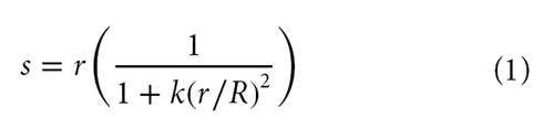
where s is the modified radial distance to a pixel that was at radius r from the center of the raw image, R is the radius to a corner of the image, and k is a radial distortion coefficient.
To experimentally determine an appropriate radial distortion coefficient k, a wire grid phantom consisting of regularly-spaced 12.7 mm squares was placed in the field of view of the fluoroscope equivalent conditions for imaging patients. The coefficient k was then adjusted until all squares on the grid appeared to be approximately the same size (Figure 1(B)) and the lines across the image were straight. This coefficient was then used to correct all subsequent images. The radius r in the present images took on a maximum value of 512√2 pixels and the k value used was 0.13. Although this approach removed nearly all image distortion, small residual distortions could still be seen (Figure 2(B)), likely because the image pixels were discretized to the grid of the original image and Equation (1) provides only first-order correction. Final corrected images had a resolution of 1024 × 1024 pixels (0.17 mm per pixel).
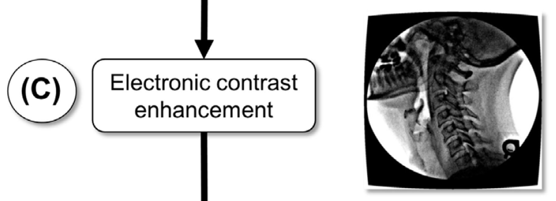
To improve the visual contrast of the geometrically- corrected images, they were enhanced using a smart sharpen filter (amount: 500%, radius: 20 pixels) in Adobe Photoshop (Adobe, San Jose, CA, USA) followed by a Gaussian blur (radius: 1 pixel) (Figures 1(C), 2(C)). This technique produced favorable tracking outcomes for the algorithm we present here, whether other techniques (Cerciello et al. 2012) to address the quantum noise in fluoroscopy images would also work, remains to be seen.
Figure 1. Procedural overview.
(A) A raw image from a sagittal-plane sequence involving flexion and extension is shown.
Pincushion distortion is evident in the superimposed yellow grid lines obtained from an orthogonal phantom.
(B) Pincushion distortion is removed using an image distortion correction algorithm (Equation 1).
(C) The contrast of each image is enhanced as described in the text.
Figure 1A.
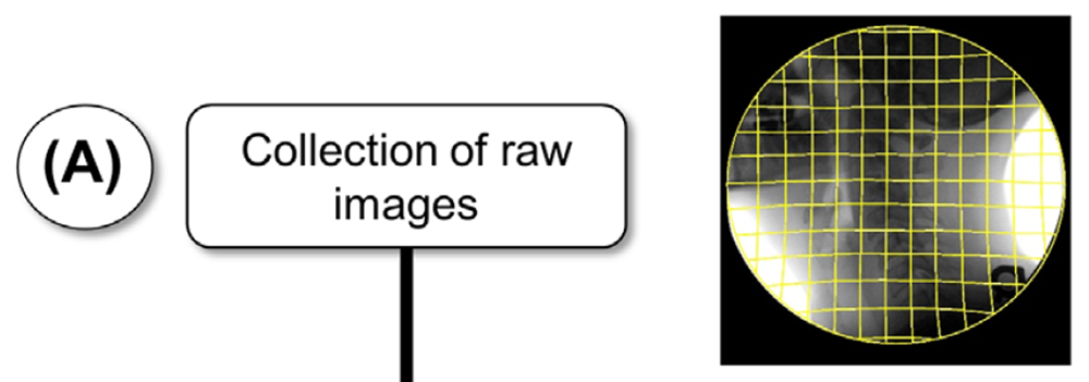
Figure 1B.

Figure 1C.
Tracking algorithms and parameters
To track the imaged vertebrae, a template-matching algorithm was used (Velduis & Brodland 1999). The technique is relatively straight-forward to implement, is well suited to tracking of semi-rigid objects, and has proven useful in a range of applications (Bootsma & Brodland 2005; Wiebe & Brodland 2005) including vertebra tracking (Muggleton & Allen 1997; Bifulco et al. 2001; Mellor et al. 2009; Cerciello et al. 2011). The technique considers a contiguous group of pixels or ‘template’ in one image and finds the best set of pixels in another image for it to overlay. Quality of fit is assessed using a normalized cross-correlation function. That function multiplies the intensities of corresponding overlapping pixels, adds these products and then normalizes the resulting score based on the average pixel intensities of the template and of the region it overlies (Velduis & Brodland 1999).
Correlation scores are calculated for each combination of location and orientation, and the parameter combination that yields the highest correlation is deemed the best match. Smaller templates generally have the advantage of high tracking precision, but if they lock on to a wrong match (i.e. ‘get lost’) the errors can be large. Larger templates significantly reduce the probability of a wrong match and have the advantage of tracking average motions reliably, but they may not follow specific points well, especially in a field that contains real or apparent deformations of the object being tracked. To realize both advantages, we developed a multi-step procedure in which large templates are used to reliably track bulk motions, followed by smaller, spatially- constrained templates that can provide tracking precision in the presence of soft-tissue-induced apparent vertebral deformations.
In preparation for the first tracking step, an operator manually selects four widely-spaced points having distinct visual features, generally the corners of each vertebral body (Figure 1(D)). A trapezoidal template is constructed (Figure 1(E)), and extended 20 pixels radially outward from each corner of the minimal trapezoid that bounds the four chosen points.
The first tracking step obtains the approximate position of each vertebra over time. The non-rectangular shape of the templates, tailored to the shape of each vertebra, prevents them from overlapping adjacent vertebrae, and the large size reduces errors associated with residual image distortion and pixel intensity noise. Reference templates (which the algorithm used to create matches in subsequent images) were approximately 150 pixels long on each side, and a new reference template was defined every 50 images (new reference template was the previously matched frame) to reduce tracking error caused by changes in apparent vertebra shape, but not after every image, as doing so would unnecessarily increase discretization- related errors (Velduis & Brodland 1999). Search parameters included whole-pixel template translations of up to 31 pixels each way from the previous template position and rotations in 1° steps up to 8° each way from the previous template orientation. Visual inspection ensured the templates matched the general motion of the vertebral bodies.
To refine the tracking, successively smaller templates based on the original large template, were defined automatically (Figure 1(F)). Briefly, a trapezoidal template is defined around each individual coordinate and incorporates the corner of the vertebral body; the coordinates are free to move independently from one-another. To prevent these templates from locking onto incorrect matches, they were constrained to move only 2 pixels in each direction in sub-pixel increments from the positions they would be expected to have based on the larger templates in the previous iteration. The reduced-size templates were not allowed to rotate from the orientation predicted by the larger template, and the reference template from the original image was used throughout the full tracking; it was not updated, contrary to the reference template update strategy for the large templates used in the first tracking step. Typically, three refinement passes were performed, with the smallest templates nominally 71 by 71 pixels and tracked to their best locations with 1/8-pixel bias. Raw coordinate data was smoothed using a 2nd order dualpass Butterworth filter with a cutoff frequency of 1 Hz as revealed by residual analysis (Wells & Winter 1980).
The residual analysis revealed the optimal cutoff frequency where the low-frequency motion signal component in the data rises above the signal from the noise component. Vertebrae translations and rotations were then calculated from the template motions in the final tracking pass (Figure 1(G)) using a least-squares approach (Veldhuis et al. 2005); this approach assumed rigidity of the individual vertebrae. From the computed rotation matrices of each individual vertebra, the relative orientation of one vertebra could be computed relative to another to provide the intervertebral angular displacement at a joint. Intervertebral joint shear was calculated using a previously defined method (Frobin et al. 1996). Briefly, a shear axis was defined which bisected two adjacent vertebrae. Vectors from the midpoint of the shear axis to the midpoint of each vertebra were then defined and from these, vectors perpendicular to the shear axis were defined. The distance between these perpendicular vectors (normalized to their initial distance) was defined as the intervertebral joint shear.
Figure 1. Procedural overview.
(D) An operator then selects one point at each of the 4 corners of each vertebral body to define the shape
of the large tracking template.
(E) A computer algorithm generates a large trapezoidal template around each vertebral body based on these
points and a first tracking pass determines the general motions of each vertebra.
(F) Three more refinement passes are performed using smaller templates around each of the original corner points.
The points move independently within a limited range.
(G) Angular and shear displacements are calculated and displayed.
Figure 1D.

Figure 1E.

Figure 1F.
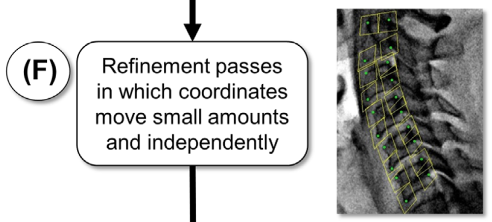
Figure 1G.

Figure 1G. Closeup

Method validation
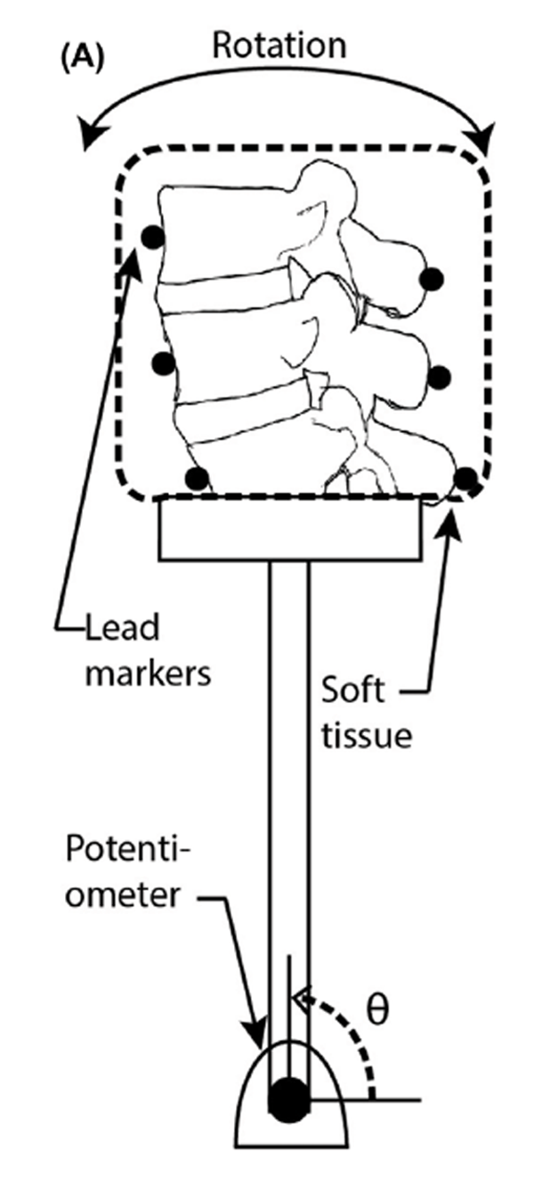
The bias of the tracking algorithm was tested by imaging a porcine spine specimen rigidly attached to a moving mechanical arm (Figure 2(A)). The specimen consisted of three vertebral bodies and two intervertebral discs (Figure 2(B)). The skin and organs had been removed, but all muscles and ligaments were left intact. Small surgical incisions were made so that lead markers could be rigidly mounted to the anterior aspect of the vertebral body and the posterior aspect of the spinous process of each vertebra using cyanoacrylate adhesive. The markers offered sufficiently high contrast under videofluoroscopy that a straight-forward cross-correlation function (Velduis & Brodland 1999) could track them with sub-pixel bias, providing rotation accuracies of 0.05° (based on two markers tracked to the nearest 1/8-pixel and separated by 200 pixels).
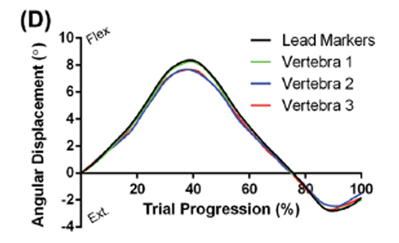
Figure 2. Algorithm validation using a porcine spine.
(A) Three porcine vertebrae with high-contrast lead markers were attached to an arm and moved through the field of view.
(B) Shown, is a porcine spine specimen with pincushion distortion removed but before contrast enhancement. The lead markers used for the reference movements are highlighted as green points.
(C) This figure shows the specimen after contrast enhancement, and ready for machine tracking.
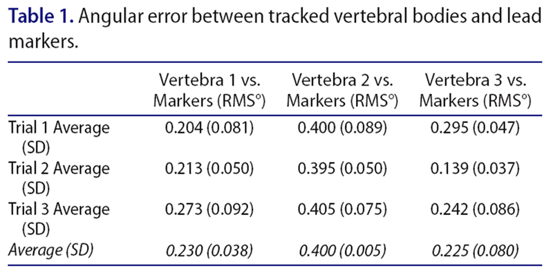
(D) The angular motions of the tracked vertebrae match well with the calculated motions of the lead markers. The maximum RMS error was 0.4° (Table 1).
Figure 2A.
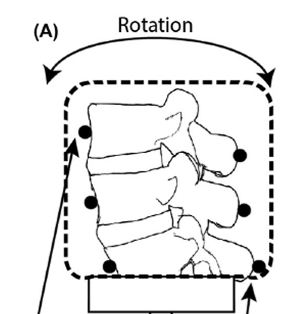
Figure 2B.
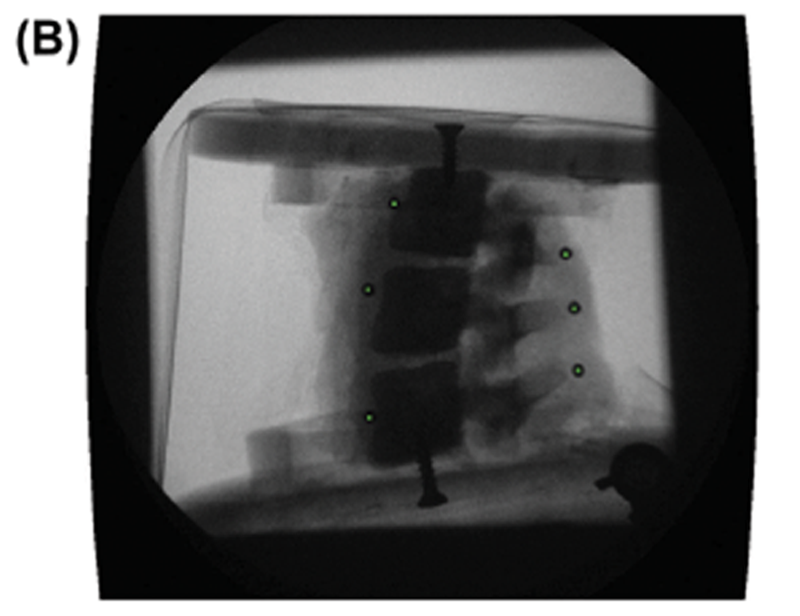
Figure 2C.

Figure 2D.
The soft tissue on the spine specimen was left intact to better mimic the in vivo situation, making the phantom vertebrae challenging to track as the attached tissue blurred the bone edges. Three trials were done, moving the phantom from one edge of the field of view to the other. The vertebrae in each of the trials were tracked independently ten times to provide 30 tracking sets for statistical analysis. Over the entire analysis, this created 90 independent vertebra tracking trials to assess the efficacy of the algorithm.
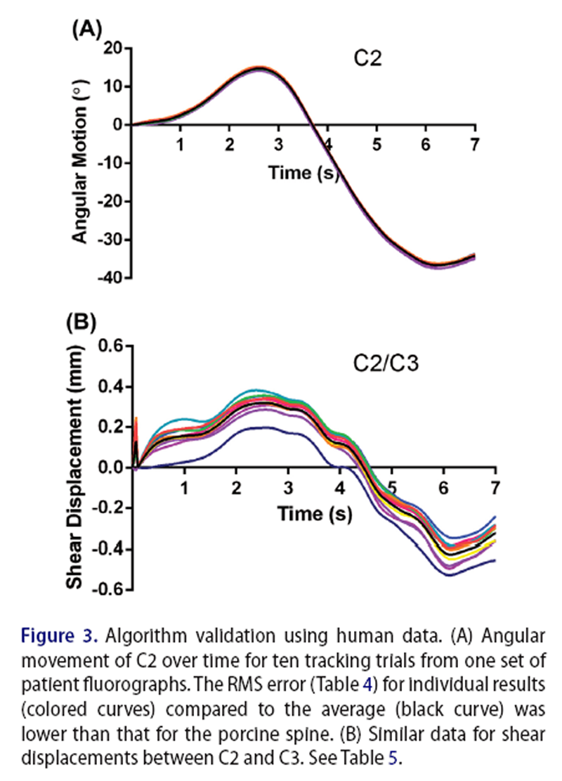
Figure 3 The algorithm was also tested by applying it repeatedly to videofluoroscopy image sets from human patients. Three in vivo image sequences of sagittal plane cervical spine flexion-extension were tracked using the algorithm. Patients gave informed consent for their image sequences to be used for research purposes, and all protocols were approved by the University Research Ethics Committee. Radiation exposure for a typical image sequence was between 0.75 and 1.5 mSv. Each sequence was tracked independently ten times, vertebral rotations and intervertebral shears were calculated (Figure 3) and tracking consistency was analyzed statistically.
To investigate the clinical potential of the approach outlined here, the algorithm was applied to fluoroscopic image sets from two additional patients. Both cases had been assessed by a clinician qualified to make radiological exams, who noted specific anatomical features and, based on clinical impression, varying degrees of disc height loss. Each set consisted of approximately 300 frames (Approximately 10 s of motion, See Supplementary Videos 1 and 2) and the algorithms outlined in Figure 1 were used to calculate vertebral motions and intervertebral rotations and shears.
Each patient was asked to start from a neutral position, flex their cervical spine fully, and then extend it before returning to the neutral position. To minimize out-of-plane motions, patients were given the opportunity to practice the desired motion prior to imaging, and were supervised by a clinician throughout the process to ensure that no deviations occurred. Their heads were also placed close to the image intensifier, and there was a barrier against their right shoulder to help act as a reference, guide their movement, and restrict it to the sagittal plane as closely as possible. In this way, we would expect outof- plane movement to be lower than what 3D approaches have previously reported (McDonald et al. 2010), as by design, movement in these devices cannot be restricted to the extent presented here while still allowing motion across three planes.
Results

Table 1
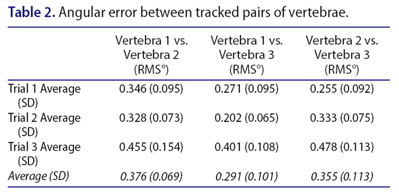
Table 2
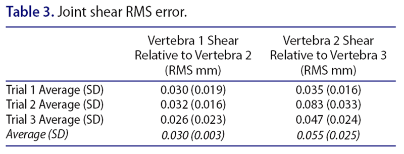
Table 3
Table 4
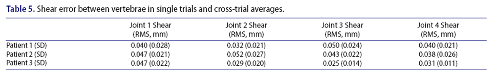
Table 5 The average RMS errors in the rotations of the superior, middle, and inferior vertebrae across the three porcine trials were 0.230°, 0.400°, and 0.225° compared to the tracking of the lead markers (Table 1). The RMS errors in the calculated intervertebral displacements, which should have all been zero, but are the result of differences between vertebral displacements and would thus be expected to have higher errors than them, by a factor of √2, are 0.376° and 0.355° for the superior and inferior joints, respectively (Table 2), while the corresponding RMS joint shears, which should also have been zero were 0.030 and 0.055 mm (Table 3). The differences between the individual patient trials and the average across all ten trials were smaller than the highest error in the porcine spine tracking results (Tables 4 and 5).
Patient Case 1 (40 years, female) presented with no anatomical abnormalities, but the individual had been in a motor-vehicle accident and complained of neck pain and headaches (Figure 4(A)). Figure 4(B) shows the angular displacements that occurred at each of the intervertebral joints versus the total degree of neck flexion or extension. If all joints moved in synchrony and proportion with each other, these curves would take the form of straight lines, with slopes proportional to the relative contributions of the specific joints. As the figure shows, three of the joints follow this general pattern, while the lowest one (C5/ C6), for reasons that are not apparent, does not. Manual examination of the associated video confirms the motions reported in the figure. The curves in Figure 4(B) also show hysteresis at each joint, a phenomenon shown in in vitro (Barrey et al. 2015), and identified here for the first time in vivo. Thus, the time course of the various intervertebral motions associated with motions away from the neutral position are not just the reverse of those associated with returning to it.
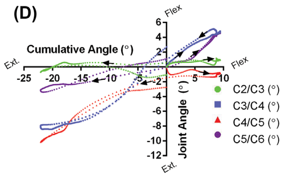
Patient Case 2 (68 years, female) had also been in a motor-vehicle accident and had complaints of neck pain and headaches. She presented with pronounced anatomical irregularities that included moderate disc height loss at C4/C5, associated loss of cervical lordosis, and severe disc height loss at C5/C6 and C6/C7 (Figure 4(C)). Osteophytic lipping was also evident at all levels that showed disc height loss. Supplementary Movie 2 shows the effect of the loss of cervical lordosis at C4/C5, and how disc height loss inhibits motion at C5/C6. During neck flexion, there was no displacement about the C4/C5 joint, a joint that contributed to the kyphotic deformity, as it was already in full flexion. During neck extension, the disc height loss at C5/C6 appeared to cause facet joint contact and prevent further extension at that joint. Comparison of the motion graph in Figure 4(D) with that in Figure 4(B) confirms the profound joint displacement differences between this patient and Case 1.
Figure 4. Analysis of two patient cases.
(A) Case 1 (40 years, female) had no disc height loss or anatomical abnormalities, but had complaints of
neck pain and headaches. Tracking points were manually placed on key locations on each vertebra
(green dots) and large trapezoidal templates were built around them for purposes of the initial tracking
pass (yellow outlines). See Supplementary Movie 1.
(B) Displacements of each intervertebral joint is plotted against the sum of the motions in all four joints
(cumulative angle) over a neutral to full flexion to full extension to neutral sequence. All joints demonstrate
some degree of hysteresis with the lowest joint (C5/C6) demonstrating the most hysteresis and difference
from the other joint motions.
(C) Case 2 (68 years, female) presented with moderate height loss at C4/C5 and severe height loss at C5/C6
and C6/C7. As with Case 1, the patient had complaints of neck pain and headaches. Osteophytes were present
at all levels with height loss and there was a kyphotic deformity.
(D) Less flexion motion was observed at the C4/C5 joint as it was already in full flexion due to the kyphosis
(see Supplementary Movie 2). Some flexion motion was observed at the C5/C6 joint, but that joint displaced very
little in extension due to facet joint interaction associated with disc height loss. The majority of motion occurred
about the C3/C4 joint, a level without height loss. All aberrant movements appear to be associated with
structural abnormalities.
Figure 4A.
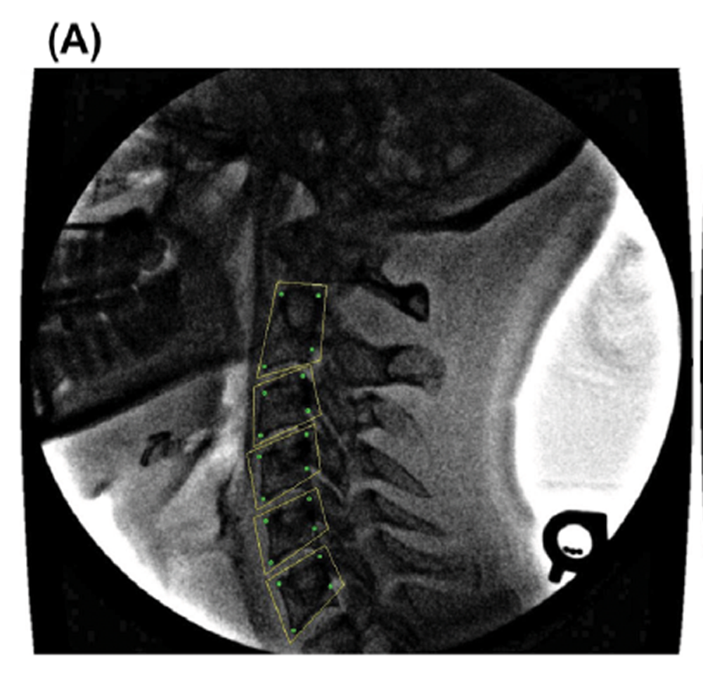
Figure 4B.
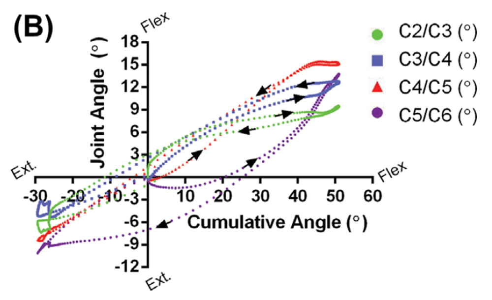
Figure 4C.
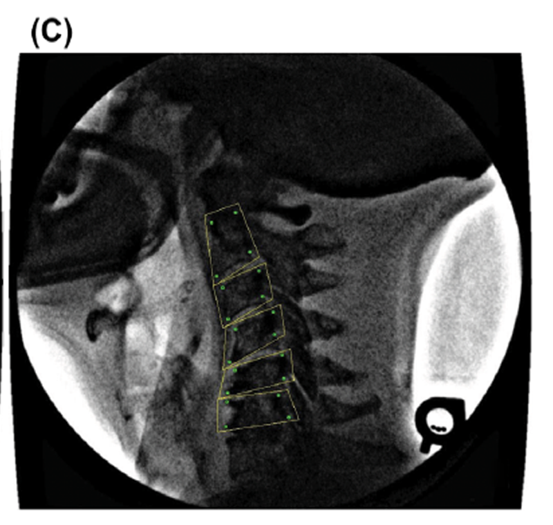
Figure 4D.
Discussion
This study demonstrates that multi-step template matching is practical to implement and that it can accurately track individual vertebrae. Compared to most other tracking approaches (Zheng et al. 2004; Reinartz et al. 2009; Wong et al. 2009, 2006), template matching is more straightforward both in concept and implementation, and although our version was coded in C++, it could be implemented without difficulty in MATLAB.
The validation protocols were made as rigorous and relevant to the clinical setting as practical. For example, substantially-intact porcine cervical spines were used, to avoid any possible advantages afforded by the clearer vertebral edges found in excised vertebrae and non-moving phantoms, or the high-contrast edges often inherent in mechanical targets. In the porcine study, ground truth was established using lead markers that could be tracked with high angular precision (0.05°) to avoid any errors or bias associated with manual tracking. Then, multiple, separate motion time courses were determined so that reliable statistical properties could be derived. In the second phase of the validation step, human vertebrae were tracked multiple times for a total of 150 different time courses – under clinical conditions that involved pincushion distortion, optical nonlinearities, soft tissue motion and associated variable blurring of the vertebral body edges, and low image contrast and noise.
Even under these conditions, intervertebral angular errors of the order of 0.4° and shear errors not larger than 0.055 mm were realized. The in vivo tracking errors (Tables 4 and 5) were smaller than in the porcine tests. These error values compare favorably with tests on static hard-tissue that produced vertebral angular errors of 0.8° (Bifulco et al. 2001), 0.6° (Muggleton & Allen 1997), and 0.4° (Cerciello et al. 2011) and mechanical targets which gave errors of 0.41° (Ahmadi et al. 2009). Additional comparisons are difficult to carry out because, while we report intervertebral angles, Wong and colleagues (Wong et al. 2006) reported angular velocities and associated errors, others (Wong et al. 2009) reported spatial positions and heir discrepancies relative to manually-identified feature points.
There are emerging techniques which have focused on measuring soft-tissue displacements and strains within the spine under MRI (Chan et al. 2014; Chan & Neu 2014). Further development of the algorithm presented here could potentially be applied towards tracking these features as well, given that the core algorithm is simply matching an image template. In this same fashion, the algorithm could also be applicable towards 3D fluoroscopy measurements, expanding its potential use as research and clinical setups become more sophisticated. Future development of the algorithm we have outlined here will hopefully enhance the breadth of its use.
Because patient fluorographs can now be more easily and precisely analyzed, vertebral motions can be studied with increased confidence, accuracy, and detail. The resulting data (such as in Figure 4) has the potential to improve understanding of the relationship between anatomical irregularities and dysfunction. In time, we hope to further understand the relationship between aberrant motions of individual vertebrae and their relationship to injury risk, degenerative change, and pain triggers. This could be used to potentially enhance and inform future clinical practice.
Acknowledgements
The authors gratefully acknowledge Dr. Edward Cambridge D.C. for his assistance in grading patient disc height loss. No commercial relationships or conflicts of interest exist in this work. Dr. John W. Baird holds the rights to the ‘Digital Motion X-ray (DMX)’ trademark in Canada.
Funding
This research was funded by Natural Sciences and Engineering Research Council of Canada (NSERC) Discovery Grants to SMM and GWB.
References:
Ahmadi A, Maroufi N, Behtash H, Zekavat H, Parnianpour M. 2009.
Kinematic analysis of dynamic lumbar motion in patients with lumbar segmental
instability using digital videofluoroscopy.
Eur Spine J. Nov;18:1677–1685. Epub 2009 Sep 04.Barrey C, Rousseau MA, Persohn S, Campana S, Perrin G, Skalli W. 2015.
Relevance of using a compressive preload in the cervical spine:
an experimental and numerical simulating investigation.
Eur J Orthop Surg Traumatol. Jul;25 Suppl 1: 155–165. Epub 2015/04/08.Bifulco P, Cesarelli M, Allen R, Sansone M, Bracale M. 2001.
Automatic recognition of vertebral landmarks in fluoroscopic sequences for
analysis of intervertebral kinematics.
Med Biol Eng Comput. Jan;39:65–75. Epub 2001 Feb 24.Bifulco P, Cesarelli M, Cerciello T, Romano M. 2012.
A continuous description of intervertebral motion by means of spline interpolation
of kinematic data extracted by videofluoroscopy.
J Biomech. Feb 23;45:634–641. Epub 2012 Jan 27.Bootsma GJ, Brodland GW. 2005.
Automated 3-D reconstruction of the surface of live early-stage amphibian embryos.
IEEE Trans Biomed Eng. Aug;52:1407–1414.Breen A, Allen R, Morris A. 1989.
A digital videofluoroscopic technique for spine kinematics.
J Med Eng Technol. 13:109–113. Epub 1989 Jan 01.Brown T, Reitman CA, Nguyen L, Hipp JA. 2005.
Intervertebral motion after incremental damage to the posterior structures of the cervical spine.
Spine. Sep 01;30:E503–E508. Epub 2005 Sep 02.Cerciello T, Romano M, Bifulco P, Cesarelli M, Allen R. 2011.
Advanced template matching method for estimation of intervertebral kinematics of lumbar spine.
Med Eng Phys. Dec;33:1293–1302. Epub 2011 Jul 19.Cerciello T, Bifulco P, Cesarelli M, Fratini A. 2012.
A comparison of denoising methods for X-ray fluoroscopic images.
Biomed Signal Process Control. 7:550–559.Cesarelli M, Bifulco P, Cerciello T, Romano M, Paura L. 2013.
X-ray fluoroscopy noise modeling for filter design.
Int J Comput Assist Radiol Surg. Mar;8:269–278. Epub 2012 Jun 22.Chan DD, Neu CP. 2014.
Intervertebral disc internal deformation measured by displacements under
applied loading with MRI at 3T.
Magn Reson Med. Mar;71: 1231–1237. Epub 2013 May 08.Chan DD, Gossett PC, Butz KD, Nauman EA, Neu CP. 2014.
Comparison of intervertebral disc displacements measured under applied loading
with MRI at 3.0T and 9.4T.
J Biomech. Aug 22;47:2801–2806. Epub 2014 Jun 28.Cholewicki J, McGill SM, Wells RP, Vernon H. 1991.
Method for measuring vertebral kinematics from videofluoroscopy.
Clin Biomech. May;6:73–78.Frobin W, Brinckmann P, Leivseth G, Biggemann M, Reikerĺs O. 1996.
Precision measurement of segmental motion from flexion-extension radiographs of
the lumbar spine.
Clin Biomech. Dec;11:457–465. Epub 1996 Dec 01.Hwang H, Hipp JA, Ben-Galim P, Reitman CA. 2008.
Threshold cervical range-of-motion necessary to detect abnormal intervertebral
motion in cervical spine radiographs.
Spine. Apr 15;33:E261–267. Epub 2008/04/12.Kirkaldy-Willis WH, Farfan HF. 1982.
Instability of the lumbar spine.
Clin Orthop Relat Res. May;165:110–123. Epub 1982 May 01.Lao L, Daubs MD, Scott TP, Lord EL, Cohen JR, Yin R, Zhong G. 2015.
Effect of disc degeneration on lumbar segmental mobility analyzed by kinetic
magnetic resonance imaging.
Spine. Mar 1;40:316–322. Epub 2014 Dec 11.Lee SH, Daffner SD, Wang JC, Davis BC, Alanay A, Kim JS. 2015.
The change of whole lumbar segmental motion according to the mobility of degenerated
disc in the lower lumbar spine: a kinetic MRI study.
Eur Spine J. Sep;24: 1893–1900. Epub 2014 Mar 29.Lin CC, Lu TW, Wang TM, Hsu CY, Hsu SJ, Shih TF. 2014.
In vivo three-dimensional intervertebral kinematics of the subaxial cervical
spine during seated axial rotation and lateral bending via a
fluoroscopy-to-CT registration approach.
J Biomech. Oct 17;47:3310–3317. Epub 2014 Sep 15.McDonald CP, Bachison CC, Chang V, Bartol SW, Bey MJ. 2010.
Three-dimensional dynamic in vivo motion of the cervical spine:
assessment of measurement accuracy and preliminary findings.
Spine J. Jun;10:497–504. Epub 2010 Apr 03.Mellor FE, Muggleton JM, Bagust J, Mason W, Thomas PW, Breen AC. 2009.
Midlumbar lateral flexion stability measured in healthy volunteers by in vivo fluoroscopy.
Spine. Oct 15;34:E811–E817. Epub 2009 Oct 16.Muggleton JM, Allen R. 1997.
Automatic location of vertebrae in digitized videofluoroscopic images of the lumbar spine.
Med Eng Phys. Jan;19:77–89. Epub 1997 Jan 01.Panjabi MM. 1992.
The stabilizing system of the spine. Part II. Neutral zone and instability hypothesis.
J Spinal Disord. Dec;5:390–397; discussion 397. Epub 1992 Dec 01.Reinartz R, Platel B, Boselie T, van Mameren H, van Santbrink H. 2009.
Cervical vertebrae tracking in videofluoroscopy using the normalized gradient field.
Med Image Comput Comput Assist Interv. 12:524–531. Epub 2009 Jan 01.Ruberté LM, Natarajan RN, Andersson GB. 2009.
Influence of single-level lumbar degenerative disc disease on the behavior of
the adjacent segments – a finite element model study.
J Biomech. Feb 9;42:341–348. Epub 2009 Jan 13.Stokes IA, Gardner-Morse MG, Henry SM. 2011.
Abdominal muscle activation increases lumbar spinal stability: analysis of
contributions of different muscle groups.
Clin Biomech. Oct;26:797–803. Epub 2011 May 17.Subramanian N, Reitman CA, Nguyen L, Hipp JA. 2007.
Radiographic assessment and quantitative motion analysis of the cervical spine
after serial sectioning of the anterior ligamentous structures.
Spine. Mar 01;32:518–526. Epub 2007 May 06.Veldhuis JH, Brodland GW, Wiebe CJ, Bootsma GJ. 2005.
Multiview robotic microscope reveals the in-plane kinematics of amphibian neurulation.
Ann Biomed Eng. Jun;33:821–828. Epub 2005 Aug 05.Velduis JH, Brodland GW. 1999.
A deformable block-matching algorithm for tracking epithelial cells.
Image Vision Comput. 17:905–911.de Vries J, Ischebeck BK, Voogt LP, van der Geest JN. 2015.
Joint Position Sense Error in People With Neck Pain: A Systematic Review
Man Ther. 2015 (Dec); 20 (6): 736–744Wallace WA, Johnson F. 1981.
Detection and correction of geometrical distortion in X-ray fluoroscopic images.
J Biomech.14:123–125. Epub 1981 Jan 01.Wells RP, Winter DA. 1980.
Assessment of signal and noise in the kinematics of normal,
pathological and sporting gaits.
Proceedings of the Proceedings of the Special Conference of the
Canadian Society for Biomechanics;
London, Ontario.Wiebe C, Brodland GW. 2005.
Tensile properties of embryonic epithelia measured using a novel instrument.
J Biomech. Oct;38:2087–2094.Wong KW, Luk KD, Leong JC, Wong SF, Wong KK. 2006.
Continuous dynamic spinal motion analysis.
Spine. Feb 15;31:414–419. Epub 2006 Feb 17.Wong A, Dunk NM, Callaghan JP. 2009.
A systematic approach to feature tracking of lumbar spine vertebrae from
fluoroscopic images using complex-valued wavelets.
Comput Methods Biomech Biomed Eng.12:607–616.Zheng Y, Nixon MS, Allen R. 2004.
Automated segmentation of lumbar vertebrae in digital videofluoroscopic images.
IEEE Trans Med Imaging. Jan;23:45–52. Epub 2004 Jan 15.
Return to RADIOLOGY
Return to SPINAL ALLIGNMENT
Since 3–20–2017

| Home Page | Visit Our Sponsors | Become a Sponsor |
Please read our DISCLAIMER |