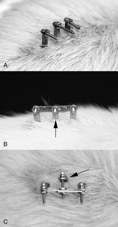
Fig 2
This figure shows the ELM with 3 link configurations.
A, Control rat SAUs were implanted but never linked.
B, Linked in neutral: links were applied with the anesthetized rat prone on a flat surface. Note the small hole in each SAU (arrow) just above the skin. In the L5 SAU, this hole was used for placement of a pin during stiffness testing. Similar holes in the L4 and L6 SAUs were not used.
C, Linked in rotation: this rat was linked as in the neutral configuration above (B), and then the L5 SAU stem (arrow) was forced into rotation relative to the 2 outer SAU stems.