Fig 3
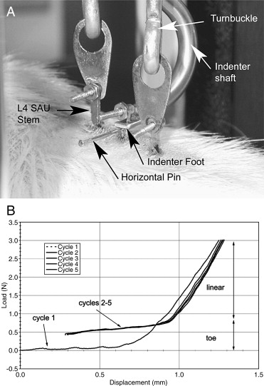
Intervertebral spine stiffness testing.
A, Load frame indenter depressing the L5 SAU stem while the L4 and L6 SAUs are supported by turnbuckle linkages. The indenter foot slides over the L5 SAU stem and rests on a small horizontal pin that has been inserted through it (Fig 2B).
B, A raw data plot from the PCM-Versa frame load platform. The long double-headed vertical arrow on the right marks the linear region of the force/displacement plot, and the short double-headed arrow identifies the “toe” region (see text).
Each stiffness test consisted of 5 cycles to a maximum of 3-N load. Cycle 1 began with no load and was always discarded from data analysis. Cycles 2 to 5 began with a 0.4-N preload. The linear region slopes of these cycles were averaged to determine the D-V stiffness coefficient (k) of the spine segment.