Life Chiropractic College, Research Department.
Presented at The 16th Annual Biomechanics of the Spine Conference
Boulder, Colorado, June 1985
Many different upper cervical techniques are in the use in the chiropractic profession today. Most use radiographs and palpation to define a vector along which a controlled force will be directed toward some osseous structure. They differ significantly, however in the amplitude and rate of the adjustive force used. Also in some techniques the adjustment is delivered by hand while others make use of an instrument.
The purpose of this work is to characterize the adjustive forces generated by adjusters and instruments. Such information may shed some light on the possible mechanisms of action of the adjustments.
The force transducer (Interface 150) measures forces in the range of 0 to 150 lbs., although the amplification is such that the voltage output is unreadable above 77 Lbs. The strain gage output was calibrated with dead weights to produce .55V per pound. The sensitivity of the A/D (Interactive Microware ADALAB) allowed resolution of .02 lbs. force.
The amplified output of the force transducer was stored in an Apple II+ computer. Software allowed collection of 1000 data points per second and immediate plotting of a six second segment of data. This data segment could be scanned and 1/4 second sub-segments stored individually on disc for later analysis and plotting.
Also measured were the forces that could be delivered by a variety of instruments used in the field. These included the cam-driven stylus of the SWRI, the spring driven Lee/Fuhr Activator, and the solenoid-driven Sweat and Laney adjusting instruments.
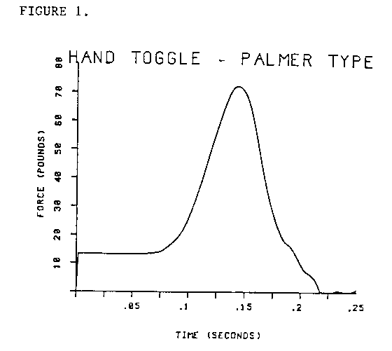
In all cases, the adjustive force was delivered directly into the headpiece and the administrator instructed to apply the same amount of initial contact and thrust as would be applied in actual adjustments. Both the initial contact (preload) and the thrust amplitude as a function of time were measured and recorded.

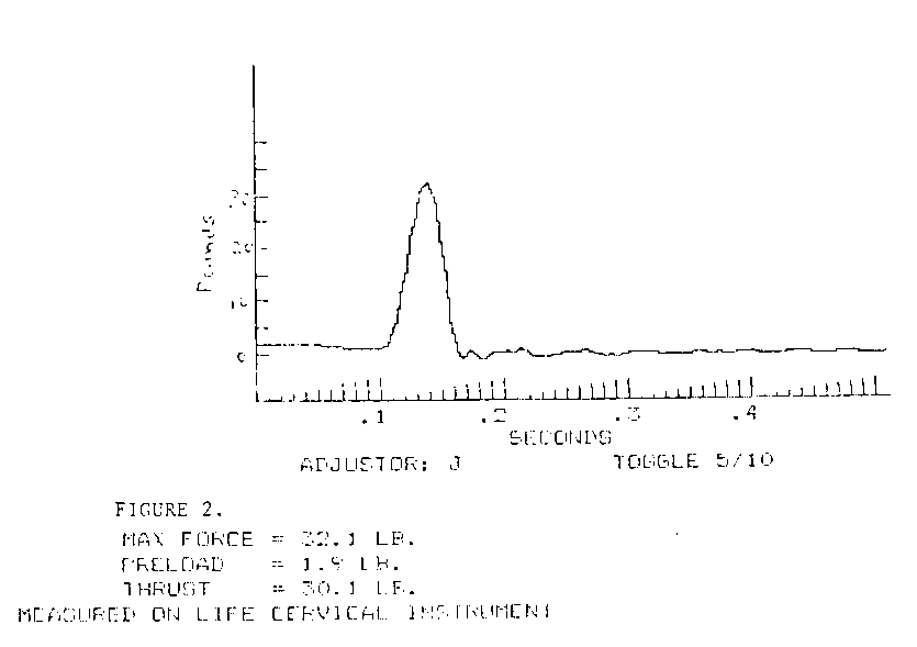
Figure 2 shows an example of a lower amplitude toggle thrust. It was noted that the thrusts were generally symmetrical, that is, the down thrust was at the same rate as the recoil. This may differ somewhat from the pattern of an actual adjustment, which is performed on a drop headpiece designed to fall away from the adjustor once some threshold force is reached.
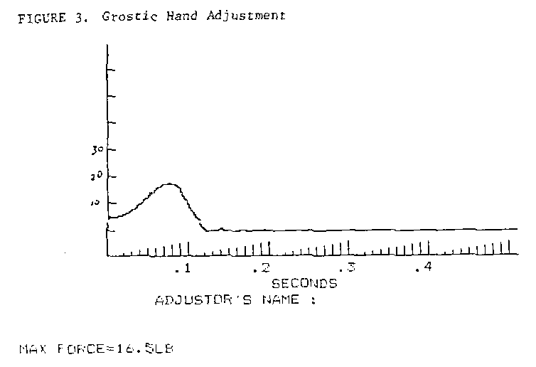
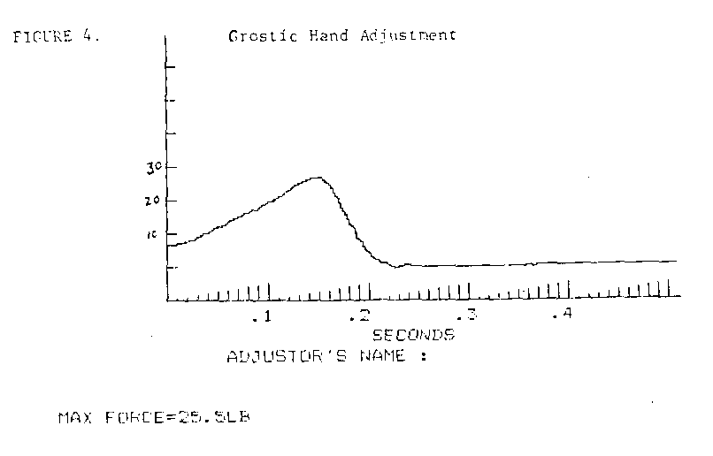
The other type of hand thrust that was recorded was that used in the Grostic Technique. The amplitudes of this type of thrust ranged from 15 the 25 lbs., with preloads from 5 to 10 lbs. The duration of thrusts varied from 100 to 200 msec. Figures 3 and 4 are representative of the Grostic style thrust. It was noted that the amplitudes of this type of thrust were more uniform from person to person than were the toggle recoil thrusts.
Instrument Adjustments:
Each of the instruments tested could produce variable thrusts. Rather than measure the full range of thrusts available, in most cases only the setting generally used in actual adjustments by the practitioners consulted were used.
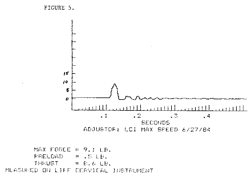
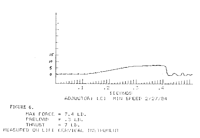
Three of the instruments were forward probing but used different power mechanisms. The adjusting head of the SWRI is powered by a rotating cam. The depth of the thrust is controlled by adjusting the amount of contact with the cam; the thrust rate can be controlled by varying the motor speed. The thrust depth used in this study was 3.2 mm. Plots of the SWRI thrust are shown in figures 5 and 6. In actual use for adjustment, the fastest stylus speed is used.
The Lee/Fuhr activator is a spring driven device that is hand cocked. The amount of recoil allowed the hammer is adjustable to provide different force and displacements at the tip. The force of the activator for this study was set at two turns of the barrel from the fully closed position. There are also two rubber tip attachments that can be used. For this study the harder, white tip was used which has a diameter of 15 mm.
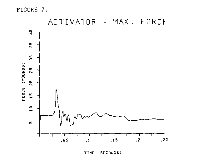
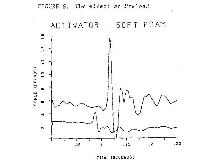
The amplitude of the activator thrust varied from 2 to 18 pounds and the time of the thrust was 12 msec. A typical thrust is represented in figure 7. The amplitude of the thrust was very much dependent on preload as shown in figure 8. A preload of 2.6 pounds produced a 4 pound thrust, whereas a 5 pound preload resulted in 16 pounds of thrust.
The Laney adjusting instrument is solenoid powered with adjustable forward thrust. A spring retracts the stylus and, because there is no sharp limit to forward displacement, the measurement of stylus movement is difficult. For this study the excursion was set at the nearly closed position, producing perhaps 3-4 mm displacement. Although there is no speed control, the excursion control also limits speed secondarily by controlling how long it takes to complete the thrust, i.e. shorter thrusts take less time.
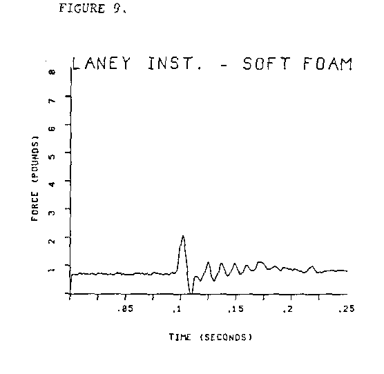
At the low setting, the Laney instrument produced thrusts with amplitude of about 2 pounds, as shown in figure 9. The instrument is also capable of much greater force: the maximum recorded was 30 pounds with a 2 pound preload.
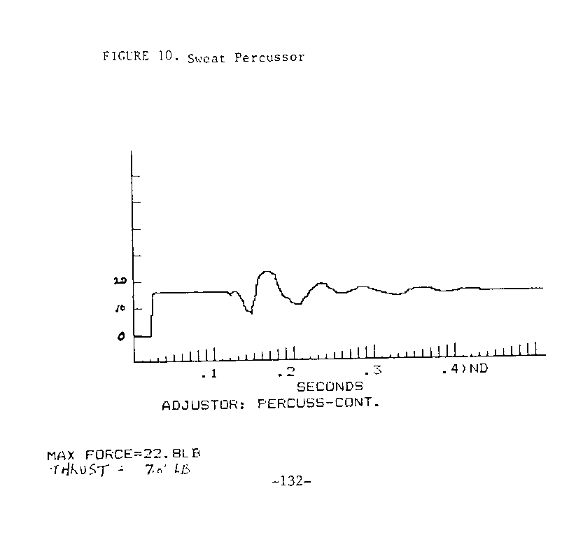
The last thrust tested was that produced by the Sweat percussion instrument. This instrument is not designed to produce forward movement of the stylus, but instead uses a solenoid accelerated hammer to strike the end of the device. In normal use the stylus is supported by a cantilever beam and allowed to contact the patient only very lightly. We could not easily match these conditions in our lab but instead allowed the stylus of the adjusting instrument to rest on the headpiece, supporting the total weight of the instrument. Hence the preload was much greater than that normally used in practice.
The resulting force output is unusual, as shown in figure 10, in that the initial activation of the device produces a retraction of the stylus, due to the inertia of the accelerating hammer. When the hammer finally strikes the bottom of the instrument it transmits about 10 pounds into the headpiece. We were unable to fix the adjusting instrument so that it would not move when activated and so could not measure the force that might be transmitted down the stylus shaft independent of forward motion. The thrust produced by the Sweat Percussion instrument probably depends significantly on how far it is allowed to travel by its supporting structure during activation.
Another possible inaccuracy exists in the measurement of thrusts produced by mechanically-activated forward thrusting devices. Human adjustors can limit the amplitude of their thrusts but the mechanical devices limit only preload and stylus excursion. The amplitude of such a thrust depends on the stiffness of the material into which the thrust is made. In our set-up, the trusts were made into soft foam covering the headpiece. The force transmitted to the headpiece transducer would not be faithfully transmitted due to the damping effects of foam.
To circumvent some of these problems, another recording scheme was used to measure the thrust of the SWRI. The adjusting head contains a force transducer between the cam and stylus shaft. Recordings of 3.2 mm thrusts into human tissue produced reactive forces in the stylus of less than 1 pound after the subtraction of a significant artifact due to the inertia of the stylus shaft. This value probably more nearly reflects the amplitude of adjustive forces produced by well supported mechanical forward thrusting devices.
Studies of the mechanical properties of the spinal segments suggest that forces of the magnitude of hand adjustments should cause large scale deformations. These deformations would take the form of a flexion of the spine with greatest deflection at the point of contact of the trust. The amplitude of deflection depends on the stiffness of the spinal articulation, which for lumbar segments in lateral flexion has been reported to be on the order of 1 degree rotation per newton-meter of bending moment [2]. If the cervical spine is one fourth as stiff as the lumbar then an 80 lb thrust applied 4 cm. from the center of the spine would produce about 0.8 degrees of flexion between vertebrae at that level.
Cineradiographic studies confirm this notion to some extent in that they have shown flexion perhaps on the order of 3-4 degrees per segment during hand adjustment of the cervical spine [3].
More accurate analysis of this situation is difficult at this time because there is a lack of data on the elasticity of the cervical spine. Also the displacements seen with cineradiography have not been accurately quantified.
Concerning instrument adjusting, it is not at all clear how the sometimes small forces used in adjusting mechanically influence the spine, especially considering the visco-elasticity of the tissue overlying the vertebrae. The portion of the thrust developed by forward probing instruments that can directly influence spinal joints is dependent on the amount of probe displacement and on the preload used to compress the tissues prior to the thrust. Under these circumstances, the effect of the thrust may be primarily neurological. A high velocity, low force impulse would stimulate phasic proprioceptors in the soft tissue of the neck. Subsequent processing of this stimulus together with other tonic proprioceptive input associated with the prestressing and placement on the table might account for the effects of light adjustment forces.