

Pierce Results System This section was compiled by Frank M. Painter, D.C.
Send all comments or additions to: Frankp@chiro.org


The Chiropractic Technique, known as the Pierce Results System, (formerly known as Pierce/Stillwagon, or PST) was developed by Vernon Pierce, D.C., Sr. It is a biomechanical analysis of spine kinematics (or spinal motion), utilizing “stress views” of the spine (flexion, extension, rotation, and/or lateral bending views where required) or videofluoroscopy (VF, or “moving x-ray” studies) to determine the loss of spinal function, which is at the core of the “vertebral subluxation complex”.
This system evolved from the earlier Pierce-Stillwagon technique (PST), which itself evolved from a core of chiropractic techniques, including Palmer HIO (Upper Cervical or Toggle Recoil Technique), Thompson, Logan Basic, and the Reaver system, with their reliance upon palpation, leg checks, and “pattern analysis” utilizing thermocouple (thermographic) instrumentation.
It is currently practiced using VF, the DT-25 for computerized thermogaphic assessment, hand and instrument adjusting, the Pierce 230 adjusting table, and may also include the new computer assisted adjusting instrument. Patient response to spinal adjusting is monitored with the use of the DT-25 or with Stillwagon's Visi-therm for changes in the pattern analysis and improvements with the “Atlas fossa” temperature. A description of thermography is available.
The Pierce Technique is an “analysis system”, it's not just another way to adjust vertebra.
The basic Doctor's equipment is the DT-25, a Precision Adjusting instrument, your hands, and access to x-ray facilities.
- A table with “drops” will improve your results.
A VF (videofluoroscopy) system will reduce patient radiation exposure, while giving you full kinematics for assessment, and finally
The computerized adjusting instrument will further assist and refine your analysis.
In 1997, Dynamic Chiropractic reported that PST was practiced by 19% of the profession. This is doubtful, unless you are counting everyone who adjusts a PI pelvis the way Dr. Pierce taught it back in the 1970's. He continued to evolve the analysis system until his untimely death in 1994. The following analysis represents the technique and system as it was being practiced at the time of his death.
The Pierce RESULTS Doctor's List is finally available online.
Search for a doctor in your State. Then check by town.
You may also want to review the other Results System website.
What specialized equipment are required?

This Zenith VertiLift Pierce Table is a variable height hylo which features a Pierce 3-D headpiece and auto-cocking dorsal and pelvic drops. Varied height selection helps to elimate back fatigue for the doctor. The Pierce table is a “full drop” table, which reduces stress on the practitioner when adjusting the neck or pelvis, and is also very easy on the patient.

The Variable Frequency Adjuster (VF Adjuster) has replaced the earlier, and now-discontinued Precision Adjuster. With this instrument, you can control the force applied, the pre-load setting, the frequency at which the adjustment is applied (4Hz-16Hz), and the number of the adjustment impacts.
Thanks to Chirp and Sigma Instruments for permission to reproduce this picture.

The DT-25 thermographic instrument is used for pattern analysis. Thermography is a means of measuring the heat (thermo) coming from a body. The Science of Thermography is the application of these heat readings for locating abnormal pathology or function in the body.
This computer-assisted instrument measures the infrared heat which radiates from our skin. Clinically, we know that your head should be about one degree warmer than your low back region. So a normal graph should slowly warm as you move from the tailbone to the back of the head.
We also compare the temperature from one side of the body to the other. We know that you have essentially the same blood supply to identical body parts (such as your right and left thumb), so the temperature should be virtually identical on both sides. A variance of more than 0.3° (three-tenths of one degree) is clinically significant [1]. (Uematsu 1988)
The computerized instrument utilizes a “force transducer” in the instrument head to analyze the “compliance” of the vertebrae while in the analysis mode. The most recent system upgrade applies a small number of “taps” on the segment, at an increasing speed, to determine the best response of the fixation component of the subluxation.
When the doctor chooses to adjust a given segment, the computer remembers the speed at which that segment oscillated best. Then, when the transducer observes a change in the resistance of the segment, it discontinues the adjustment. This is a highly effective use of computer feedback, as well as helping us monitor where and when to adjust, and the response of the vertebra to the adjustment!
A Synopsis of the Technique, including the basic “theories and principles” of why the technique works
This technique is based on the knowledge of the art, science and philosophy of chiropractic. The specifics of the analysis itself are below.
Structure and Function Our spine is a “structural” unit. There are 4 curves to the spine. Loss of structural integrity and/or normal function of the spine is the basis for the evolution of the vertebral subluxation.
Abnormal stresses occur in the facets, discs and supporting tissues when normal motion of the spine is impaired. The Pierce System analysis is aimed at locating the specific segments which are subluxated, as well as providing the means to “free” those segments.When normal function returns, the neurologic and other components of the subluxation complex resolve by the normal healing power referred to historically as “innate intelligence” or “vis medicatrix naturae” (the healing power of Nature).
Once structural abnormalities, pathologies, and positional errors are addressed on the x-rays, chiropractic analysis begins as follows:
Part I: Cervical Film Analysis
NOTE: It is advisable to use 10 x 12 film for the stress views
(flexion, extension and rotation).
The A-P View:
The spine should be straight and all spino-laminar junctions should be midline. There should be no lateral tilt to the head.
The Open Mouth View:
Teeth must not overlay the occipital condyles for the “classic” upper cervical Palmer analysis of C1 and C2 for laterality and/or rotation.
You will note that the posterior arch of C1 overlies the lateral masses (LM) of C1. A triangular portion of each LM will be observed below the posterior arch. Increased size of one of these triangles would suggest posterior rotation of Atlas on that side.
Neutral Lateral Film Analysis:
The normal cervical lordosis (which extends from C1 to T2) should have a 17-24 cm. radius, based on the patient's height. This is easily measured with the AcuArc ruler.
Kim Christensen D.C. in his book “Clinical Chiropractic Biomechanics” states:“Spinal biomechanical stability requires an optimal lordotic structure. The lordotic cervical & lumbar spine are the basis of the spine's ability to resist axial (gravitational) stress.
A resistance factor in mechanical structure is expressed by the formula:R = C2 + 1
where R = resistance to axial pressure and C = # of curvatures.
Thus, the spine's ability to resist axial stress, taking into account the Cervical, Thoracic & Lumbar (3) curves is:R = 32+ 1 = 10
If you diminish the cervical or lumbar curves, the formula suggests:R = 22 + 1 = 5
This formula demonstrates that the loss of either the cervical or lumbar curve can result in a 50% reduction in the structural strength of the spine (it's ability with withstand axial stress).

To define the cervical curve of the spine with a compass:
1. Dot the posterior inferior aspect of C1's anterior arch. (See Figure 2)
2. Dot the anterior superior aspect of the vertebral body of T2. (See Figure 2)
Figure 1
3. Set your compass for the distance between these 2 points. This length becomes the “chord” length of that patient's curve. (See Figure 1 + 2) Now, swing an arc backwards (behind the vertebra) from both points (C1 and T2), maintaining that same chord length. Where these 2 chords intersect, they create the “radius point” for describing this patient's “normal” cervical curve. (See Figure 1 + 2)
Set the compass on the radius point, while maintaining that same chord length. Swinging an arc, you should be able to define a curve at the front of the vertebral bodies, which will define the optimal cervical curve for that person. (As in Figure 2). Ideally, all the vertebra should remain on this line. The chord length will be between 17 to 24 cm., depending on that person's height.
Neutral Lateral Film Analysis:
Figure 2
The picture on the left is an example of perfect cervical lordosis. All segments should remain on Georges's line (one curved line). There should be an even spacing between each spinous process. Positioning of the head and spine should also be assessed for anterior head placement (also known as Forward Head Posture). The normal cervical lordosis (which extends from C1 to T2) should have a 17-24 cm. radius, based on the patient's height. This is easily measured with the AcuArc ruler.
The posterior arch of Atlas should be centered in the space between occiput and the C2 spinous process. If C1's posterior arch “crowds” occiput, it is labelled as an “inferior” Atlas. If it crowds C2, it is labelled “superior”. The normal Atlas Plane line should be 18-24° superior to the bottom of the film. A line under the bottom of the C2 body (Whitehorn's line) should be parallel with the bottom of the film.
This is a section of a neutral lateral cervical film, demonstrating C3 through C5.
The vertebral body is on the right. Protruding directly off the back of the body is the pedicle, which is where the ring of bone that houses the spinal cord attaches on both sides.
Directly behind the pedicle is the trapezoidal-shaped articular pillar. You will note the flat facet (zygapophysis) on the top and the bottom of each pillar. In the cervical region, they face forwards at a 45° angle.
You will also note in the following flexion and extension views that the principal motions take place at the facets. The only motion that should take place at the vertebral discs is anterior compression during flexion, and posterior compression during extension. No translation (forward or backwards motion) of the vertebral bodies should occur during these motions, as long as the disc and the longitudinal ligaments retain their integrity.
You may refer to the The “Spinal Motion Unit” section of Spinal Anatomy 101 for an in-depth review of these biomechanical phenomena.
Flexion Film Analysis:
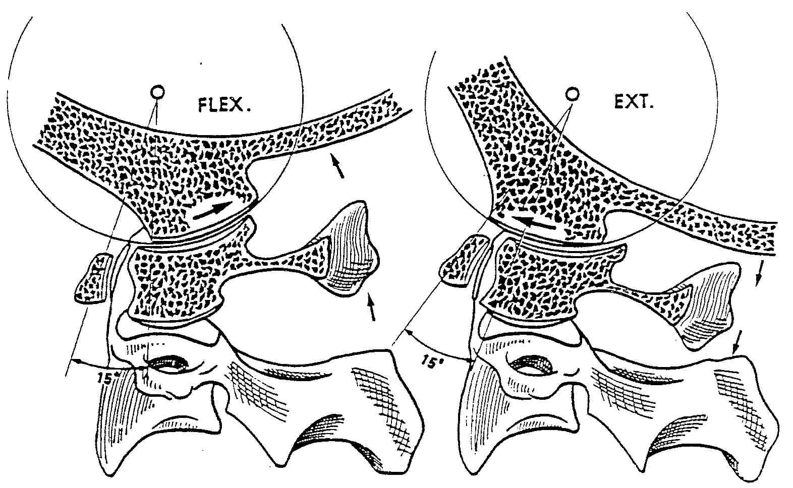
NOTE: When pre-positioning the patient for this view, it's KEY to have them first lower their chin before they flex their spine, otherwise you may not observe motion at occiput. The picture on the left demonstrates “nutation” at occiput.
Occiput reproduced with permission from
Physiology of the Joints, Volume III
by I. A. Kapandji, MD

The picture on the left is an example of perfect cervical flexion. When the spine flexes, it should fully reverse the cervical curve.
Three primary motions should occur in flexion:(1) The zygapophyses (facets) should slide upwards and forwards.
(2) Because of this motion, the IVF's should open (more) fully. And lastly,
(3) the spinous processes should “fan out”, or separate. Occiput should flex forwards, and the posterior arch of C1 should approximate the back of occiput.In flexion, George's posterior body line should be one curved line, and all segments should be on that line.
If you require more than one line to connect all the segments, the subluxated segment will reside in the portion of the spine which is straightened.
In a flexion lock, typically the segment just below the intersection of these 2 lines is the subluxated (fixed) segment.
The most obvious indicator would be that the segment fails to flex and thus, increase the size of it's IVF.
These are Dr. Pierce's Flexion Rules:
1. In flexion, all vertebra should lie on one curved line.
2. If it takes 2 lines to connect the vertebra, the subluxation is located in the straightened section.
3. Typically, the fixed segment is directly below the intersection of the 2 lines, and you should use the IVF, and the facet and spinous process motions to confirm that.
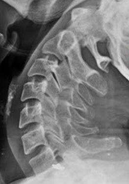
Extension Film Analysis:
NOTE: When pre-positioning the patient for this view, it's KEY to have them first raise their chin, before they extend their spine, otherwise you may not observe motion at occiput.
As with flexion, 3 thing should occur. The facets should slide backwards and down, the IVF's close down, and all the spinous processes should approximate. Unusual findings may include a segment which remains in flexion (or moves into flexion while the other segments extend). This abnormal motion is referred to as “paradoxic motion”, and is considered a sign of abnormal function of the cervical spine.
Again, all segments should remain on one curved line. A segment which will not extend is described as being “locked in extension”. Two or more lines would be needed to connect all the vertebral segments, and the subluxated vertebra will be located in the straightened section of the spine.
In this particular extension film, you may observe that C7 FAILS to extend on T1. Note the IVF size, and the fact that the spinous process fails to approximate with T1.
It's hard to see in this view, due to the overlapping of shoulder tissue, but the inferior facet of C7 fails to slide down on the superior facet of T1. A "spot view" with increased penetration could easily display this loss of function, BUT that is NOT necessary — the IVF and spinous process clearly tell the story — this is classic "paradoxic motion".
The obvious segment to adjust would be the one BELOW the one which fails to extend. You can't adjust the upper one from the front, to drive it back and down, but you can adjust the lower one P-A, to drive it forwards and up. Remember, the subluxation occurs at the facets on the bottom of the segment which fails to extend. So moving the segment directly below it (the subadjacent segment) will break up the fixation between them, and will permit the upper segment to extend, and for that IVF to close down.
Rotational or Lateral Bending Film Analysis:
Click on graphic to increase size.
When the neck either rotates or laterally bends, components of both side-bending and axial rotation occur simultaneously. This is referred to as “coupled motion”
This “coupled” motion is well described in White & Panjabi's “Clinical Biomechanics of the Spine” (pg. 53-55).
In the cervical spine, the spinous processes must move opposite to the motion of the face. That is, if you look to the right, the spinous processes must rotate to the left.
Loss of coupled motion in a segment is an indication of subluxation.
This sketch is from page 104, and describes the differences in coupled motion patterns at different spinal levels.
Part II: Pelvic Film Analysis
The A-P and Lateral Lumbopelvic Analysis:
Normal A-P View
Normal Lateral View In the normal pelvis, on the A-P view, the femur heads, the sacral base, and the iliac crests should all be level.
When you draw a line across the top of the femur heads (Femur Head Line, or FHL), a line perpendicular to the FHL, passing through the second sacral tubercle, should bisect the symphysis pubis, dividing the pelvis into 2 equal halves. The lumbar spine (in the A-P view) should be straight, with no body rotation in evidence.
Sacrum should float about 1- 1½" above the symphysis in the pelvic opening. The pelvic opening should be heart shaped. The obturators should be almond shaped and equal in size and shape. The bottoms of both ischial tuberosities should be level (equidistant from the bottom of the film).
On the lateral view, all the anterior bodies should be on a curved line with a radius of 22-30 cm, based on the patient's height.
The PI (or Posterior Inferior) Pelvis:
The PI Pelvis
Lateral view of a PI Pelvis In this PI Pelvis, you will observe:
- The left ilia is normal. (Editor's Note: Chiropractors look at films, as if we are looking at the patient's back, so that the patient's left side is on our left. Radiologists look at films “Anatomically” (facing you) so that THEIR LEFT is on YOUR RIGHT).
I believe this leads to confusion, and perhaps helps to explain medical mis-adventures, wherein the surgeon removes a non-diseased (bilateral) organ or appendage by mistake.
- On the right the ilia has rotated posterior and inferior (or PI). Note the short leg on that side, and that the sacral base is inferior on the right. (see arrow D) Because of that, the lumbar bodies have all rotated to that side.
- You also note that the obturator on the right is taller and wider (arrow C), the ilia is narrower (arrow B), and the ischial tuberosity is lower on the PI side. (arrow E)
- On the lateral view, you will observer hypolordosis, and the sacral base moves posterior
- To correct this pelvis, first adjust sacral posteriority on the major (right) side. Then adjust the ilia on the short leg side as a PI listing
The Bilateral PI Pelvis:
Bilateral PI Pelvis In the PI Pelvis, you will observe:
- The pelvic opening becomes shorter vertically
- Both obturators become taller vertically
- Sacrum sits low in the pelvic opening
- On the lateral view, you will observer hypolordosis, and the sacral base moves posterior.
- If both ilia rotate posterior to the same degree, there will be no short leg
- To correct this pelvis, first adjust sacrum as a base posterior. Then adjust both ilia as a PI listing.
The Bilateral PI Pelvis with a Major:
The Bilateral PI Pelvis with a Major In this PI Pelvis, you will observe:
- Both ilia are PI, but the major misallignment is on the right, where the leg is shortest.
- Sacrum is inferior and posterior on the major (right) side, where the ilia has rotated more posterior that on the opposite (left) side.
- The lumbar bodies have all rotated to the major (right) side
- On the lateral view, you will observe hypolordosis, and the sacral base moves posterior
- To correct this pelvis, first adjust sacral posteriority on the major side, then adjust the PI pelvis on the short leg (major) side. If the legs go even, stop there. If the other leg then goes short, adjust the other side as PI
The AS (or Anterior Superior) Pelvis:
Bilateral AS Pelvis
Lateral view of an AS Pelvis In the AS Pelvis, you will observe:
- The pelvic opening becomes taller vertically, with an hourglass shape
- Both obturators become shorter vertically
- Sacrum sits high in the pelvic opening
- On the lateral view, the sacral apex moves posterior, and the lumbar curve becomes hyperlordotic.
This is an uncommon (infrequent) listing, and a typical mechanism of injury would be a front-end collision. When the car is struck from the front, the driver's seat accelerates backwards. Because the ischial tuberosities are planted on the seat, this forces them backwards, and rotates the ilia forwards.
The IN-EX Pelvis:
The “True” IN-EX Pelvis
- The left ilia is IN, with the short leg on that side
- The right ilia is EX, and sacrum favors that side
- There is no lumbar body rotation
- The obturator is much wider on the EX side
- To correct this pelvis, adjust sacrum P-A on the EX side.
The Lateral Lumbar Film Analysis:
Normal Lateral View
The lumbar curve should have a 22-30 cm. radius. All segments should remain on George's line. Disc spaces should be uniform. Femur heads should overlap.
Lateral Bending Film Analysis:
In the lumbar spine, the motion is opposite what occurs in the cervical spine. The spinous processes must move to the side the patient leans to. If you lean to the right, the spinous processes must rotate to the right. Please refer to the Rotational Film Analysis section for more information.
Length of Time Required to Learn This Technique:
Attending the beginner and advanced seminar offered @ Palmer Davenport, or a 4 day intensive seminar is the minimum proficiency requirement. The seminars are hands on as well as textbook. Full analysis and review of each attendee's VF studies, along with their own spinal adjusting is a typical component of each seminar. The “Results” textbook is an additional tool for review.
Certifying Body's name:
The technique is taught @ Palmer and Life College, and is accredited as continuing education when taken by field doctors. To learn more about the technique, contact: Palmer College @ (800) PCC-ALUM, at their Continuing Education Department, or call Chirp @ (407) 682-1880 or at Chirp's website
Equipment needed to perform the technique:
The Acu-Arc ruler is $35
The “Results” manual is about $125
The Variable Frequency Adjusting Instrument is about $1700.
There are 2 versions of the computerized instrument, ranging from around $9000 and up.
There are various VF systems available from the mid $30,000's and up.
Ones that also take hard copy are on the high end ~ $65,000
Return to ChiroZINE
Return to CHIROPRACTIC TECHNIQUE
Since 9-01-1998
Updated 1-05-2026


| Home Page | Visit Our Sponsors | Become a Sponsor |
Please read our DISCLAIMER |